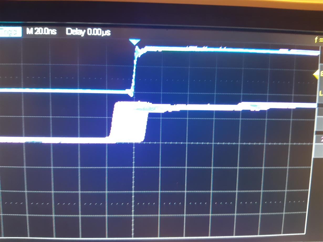
Hello!
I got the eval boards.
I can not in any way generate a synchronous 10Mhz with pps (1 Hz 50%) with the file for tics_pro you sent me.
In the video you can see the 10 Mhz that doesn't lock with the pps.
This thread has been locked.
If you have a related question, please click the "Ask a related question" button in the top right corner. The newly created question will be automatically linked to this question.
Hello!
I got the eval boards. I can not in any way generate a synchronous 10Mhz with pps (1 Hz 50%) with the file for tics_pro you sent me. In the video you can see the 10 Mhz that doesn't lock with the pps.
And also the out7_P where 1250Hz is present is always asynchronous w
ith the pps.
An UPDATE:
i can lock a 10Mhz out and 1Khz out if i use a REF1 at 100Hz.
Why not work at 1Hz ref1 also?
Hi Luca,
The 1pps input won't work with the default 48.0048MHz XO on the board. You'll need to change the XO to TCXO or OCXO (for example, < 4.6ppm for 12.8 MHz XO). Note that this 4.6ppm is with regards to the DPLL reference. So your DPLL reference must also be accurate.
For sanity check, you can first frequency synchronize the XO and the reference (use external XO port), see if everything locks. After that, you can use some real TCXO or OCXOs.
Another thing is that we've developed a much cleaner wizard for the LMK05318B. You can download the latest Ticspro, find LMK05318B, and in the first wizard page choose "backward compatible" and use that wizard to generate LMK05318 configurations.
Regards,
Hao
In fact, I abandoned the lock tests with the pps.
In no way, even with an ocxo (very precise) at 10Mhz did I manage to make the dev board work.
 configured in single ended, with a 500Kz square wave coming from a GPS (about 20nsec of jitter).
Hi Luca,
I recommend you use the latest wizard for LMK05318B to generate the configuration, since that wizard is much cleaner and easier to understand. I'm attaching a config for that profile. You'll probably download the latest Ticspro since that profile was added quite recently.
GPS_neo7_48Mhz_500Khz_1250Hz_Hao.tcs
However, it is common to have wander at the output. As long as it does not go outside of the DPLL phase unlock threshold, it is considered as phase locked. Please read through the text in the last wizard page for LMK05318B. It has detailed information on what status registers to look at. You can also click "show instructions" on each wizard page to know more about the device.
Regards,
Hao
Hi Hao!
The file you sent me doesn't work in the dev-board.
During this time I made many tests and in the end I managed to get what I wanted.
I have 1 GPS with 100pps output, and I get a synchronized 400Hz output on out7.
1) 100HZ lvttl (0V -2.7V on 50 ohm) on REF1
2) Default Xo 48.000xx Mhz (Xo set as CMOS)
3) OUT7 400Hz cmos + - aligned with ref1 (rising edge)
I attach the file that works well for me if someone needs it.
I noticed an anomaly on the software though:
The value of the time calculated in the delay window by the gui is twice that of what I measure with an oscilloscope.
If the gui tells me 300nec I measure 150nsec
Hi there,
The config that I attached were for the "B" version of software that I recommended, so it cannot be loaded to the non-B version of interface. Regardless, I'm glad that you made it work.
Thanks for the note of the ZDM delay. I'll look into the calculation.
Regards,
Hao
yes, I confirm that I used the revB of the gui.
Have you tried the configuration you sent me on the dev board and confirm that it works?
Hi Luca,
No I didn't try it on a board. Let me know if you still need me to do so.
Regards,
Hao
Hi Luca,
Sorry I haven't been able to look into this. Let me try and check it by next Tuesday.
By the way, I did find that LMK05318B's "backward compatible" mode has a software bug so that DPLL_LOFL cannot be cleared. We'll fix that asap. For now just use the LMK05318 GUI.
Regards,
Hao
Hi Luca,
I checked that the calculation for the phase offset is correct. We have limited lab access right now to perform this test, but this have been logged into the tracking system. Thanks for the feedback.
Regards,
Hao