This thread has been locked.
If you have a related question, please click the "Ask a related question" button in the top right corner. The newly created question will be automatically linked to this question.
Replies: 2
Views: 68
Part Number: BQ32000
Hi team,
My customer measured the backup supply current and found it was up to 80uA, then we found the description that VCC pin must be initialized after every total power loss situation in datasheet, section 8.2.2.3 Utilizing the Backup Supply.
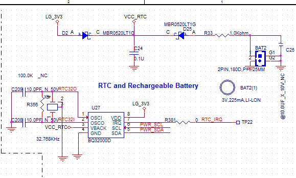
Does it mean we need to apply an additional 3.3V, >1ms pulse at VCC after VCC is not powered? Could you please suggest how to implement the initialization based on the schematic below? Thanks for your support!
Best regards,
Sam Ting
Hi Sam,
My coworker will get back to you tomorrow.
Regards,Hao
Clock and Timing Systems & Applications
To view training videos on Clock and Timing Solutions please visit TI Precision Labs
More information Clock and Timing System products: http://www.ti.com/clock-and-timing/overview.html
In reply to Hao Z:
Yes that is correct: you need to apply an additional 3.3V, >1ms pulse at VCC after VCC_RTC is applied to VBACK. You could apply VDD and VBACK for >1ms during system initialization after power-up.
Kind regards,Lane
____________________________________________________________________________________
Learn more about clocking fundamentals by watching the TI Precision Labs: https://training.ti.com/ti-precision-labs-clocks-and-timing