Hi Team,
Can you advise me my question bellow.
I tried to tune loop filter of LMK03328 referring the document
titled “8508.PLL Performance, Simulation, and Design (2).PDF”.
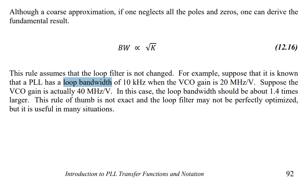
The equation 9.1 says Fc is proportional to the square root K.
Can you let me know how this relationship is concluded?
Please let me know if my thought bellows are correct or not
G(s) = ( K * Z(s) )/ s
K : products of the phase detector gain and VCO gain
Z(s) : Loop filter impedance
To get the frequency Fc on which the G(s) = 1
1 = ( K * Z(s) )/ s
It can be reformed as bellow
2Pi*Fc = K * Z(Fc)
The second order filter consist of Cp and Rs+Cs.
If Cs >> Cp, it may be almost equal to Rs +Cs
2Pi*Fc = K *(Rs + 1/2PI*Fc*Cp)
(2Pi*Fc) **2 = K *(2PI*Fc*Rs + 1/Cs)
From this equation, I understand that Fc is proportional to Rs and
invers-proportional to the square root of Cs.
However, I cannot say that Fc is proportional to the square root of Cs,
because K has two terms, 2PI*Fc*R and 1/Cs.
How you can conclude that Fc is proportional to the square root K.
Mita