This thread has been locked.

If you have a related question, please click the "Ask a related question" button in the top right corner. The newly created question will be automatically linked to this question.

LMX2571: 180 deg shift in output

Part Number: LMX2571
Other Parts Discussed in Thread: LMX2594, LMX2572, LMX2572LP, TICSPRO-SW

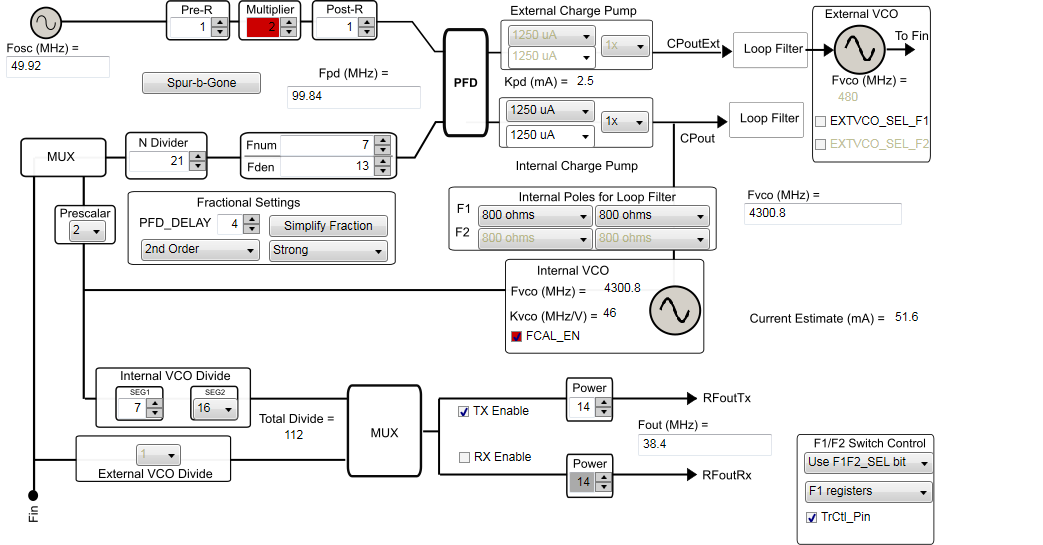
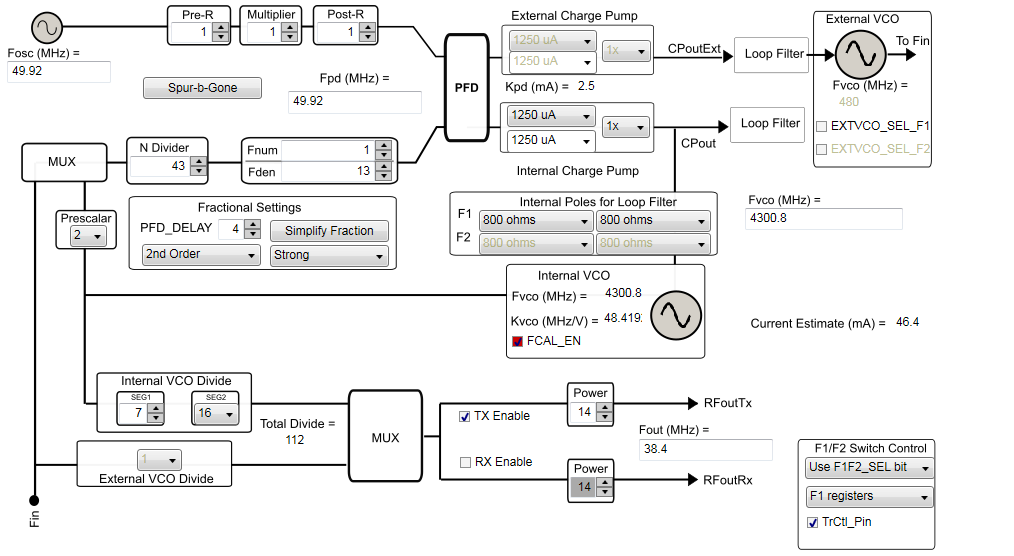
I'm using LMX2571 as a carrier recovery stage - 49.92 MHz CW in at ref input, and 38.6 MHz out. It's running ok but occasionally there's a brief drop - in ms - in 49.92 input level. The PLL output suddenly shows a 180 degree phase shift (lock detect stays 'on'). I understand this PLL uses a phase-frequency detector so that should not be a problem. Is it possible that one of the input multiplier/divider stages re-starts at the opposite phase (both dividers at 1, multiplier at 2) or is there some other phase ambiguity stage in the PLL? Obviously I'm going to stabilize the input level but it would be useful to know what the underlying PLL characteristic is.

Thank you

  • Hello Bob,

    Can you elaborate on your design?

    What is the frequency of the phase detector and VCO in your design? If you are using TICSPro if you could provide a configuration file or screenshot of the settings that would be good.

    What I get from here is that Fosc = 49.92, Pre-R = 1, Multiplier = 2 and Post-R = 1. This isn't valid because the multiplier input must be between 10-30 MHz. Am I interpreting what you described correctly?

    See the specification for "fMULTin" in the "6.5 Electrical Characteristics" section of the datasheet.

    Thanks,

    Vibhu

  • Hi Vibhu,

    You are correct. I obviously missed sect 8.1.9 in the data sheet and chose to ignore the red label in TICS Pro. I'll re-configure the input dividers. I'll try that out and see how it goes. Do you feel that this is the root of the problem?

    Thank you

    Bob

  • Is it OK to set Pre-R, MULT and Post-R to 1, and apply 49.92 MHz direct to the phase detector?

  • Hello Bob,

    It is a possibility. Good to eliminate issues with the configuration before we access the behavior of the PLL.

    Yes setting all the input path dividers and multipliers to 1 and using a phase detector frequency of 49.92 MHz is okay.

    Please let me know what you observe with the new configuration.

    Thanks,

    Vibhu

  • Hello Vibhu,

    I reconfigured the input mult/divide stages to 1, thereby applying the 49.92 MHz directly to the phase detector.. Everything looks ok but the 180 degree phase shift is still occurring when there is a brief REF signal drop in amplitude. It was also observed at one point that the phase shift was a random value other than 180 deg but we did not see a repeat. Does this configuration bypass the input stages, thereby eliminating them as possible 180-degree ambiguity generators?

    Thank you

    regards,

    Bob

  • Hello Bob,

    When you say phase shift are you comparing your input and output phase? When you use the "Internal VCO Divider" SEG1 and SEG2, you shouldn't expect the output to have deterministic phase with respect to the input.

    Also can you please send me a screenshot with your new configuration.

    Thanks,

    Vibhu

  • Hello Vibhu,

    I'm comparing the output phase to the phase of the 38.4 MHz TCXO which drives the radio so it's basically the same as comparing the output phase to the input phase.

    I'm surprised to hear about the relationship between the Internal VCO divider and the input. I can see how that could happen, but I had assumed that with the VCO running continuously that the output dividers would be locked to the VCO.

    I've attached a screen shot of the newest configuration.

    Should I be looking at a 0-delay jitter cleaner (for example) to do this?

    Thank you

    regards,

    Bob

  • Hello Bob,

    Once the output is running the phase shouldn't change. The output should have a rising edge at each rising edge of the FVCO. However the output may not have a rising edge at each rising edge of the Fosc (input). On subsequent power cycles/re calibration the output divider might sync to a different rising edge of the VCO hence creating a different input to output phase.

    We do have some LMX PLL devices that have a sync feature such as the LMX2572, LMX2594 and some other devices.  The sync feature is divided into different categories based on the frequency plan and for configurations where the Fout is not an integral multiple of the Fosc a timing critical SYNC signal can be provided to the device to synchronize the output.

    Thanks,

    Vibhu

  • Hello Vidhu,

    I think we've resolved the issues around this particular configuration, and it looks like the LMX2572 would be the way forward. Before leaving the LMX2571 behind however, I'd like to investigate one more possibility for achieving phase continuity between ref input and RF out. This assumes that the following statements are true:

    1. The output of the N divider is always locked to the Ref input, ie phase continuous after a brief disruption in the Ref input.

    2. The output of the internal VCO Divider is not necessarily locked to the same rising edge because it can start anywhere.

    I don't know if it's possible to bypass the internal VCO Divider, but if we could then the raw VCO output would appear at RF out. We could then put a synchronous frequency divider at the output which should maintain phase continuity. I'm not sure yet if there are any such devices readily available for 4.3 GHz but if we can bypass the VCO divider it would be an interesting experiment.regards,

    Bob

  • Hello Bob,

    1. The output of the N divider is always locked to the Ref input, ie phase continuous after a brief disruption in the Ref input.

    If you change the N-divider frequency a tiny bit (introduce a ppm error) the output of the reference input will change accordingly and stay locked. I'm not sure if I understand what you mean by phase continuous here. If the reference is removed, the VCO frequency will no longer be locked and will drift.

    2. The output of the internal VCO Divider is not necessarily locked to the same rising edge because it can start anywhere.

    Unfortunately there isn't a way to bypass the dividers between the VCO and outputs on this device. The VCO cores span from 4.3 GHz to 5.376 GHz however the output frequency range is 10 MHz to 1344 MHz. The minimum divide value of 4 is needed.

    If the device can bypass the output divider (post VCO dividers) the output will be at a deterministic phase with respect to the VCO. However this does not mean the output will be at a deterministic phase from the input (Fosc) unless it can be synced with a sync signal. There are also times where you cannot achieve deterministic phase between input and output even with a sync signal. Please see "Category 4" in "Figure 170. SYNC Category" of LMX2572 datasheet.

    The LMX2572 has the ability to have a direct "raw" VCO output and the VCO frequency range includes 4.3 GHz. So this may meet your requirements. If you use a Fosc frequency of 100 MHz or a frequency that puts the device in "Category 1a" in "Figure 170. SYNC Category" you will see that the input and output are inherently deterministic without a sync mode.

    Thanks,

    Vibhu

  • Hello Vibhu,

    I think we've gone as far as we can with the LMX2571. I'm preparing to migrate to LMX2572. As I understand, the primary difference between the '2572 and '2572LP is that there is no SYSREF capability in the '2572LP  If I understand correctly, SYSREF is not needed to establish deterministic delay between REF input and RF output.

    The RF output for the '2572LP is set at 2 GHz max o/p and I'd thought that the VCO would also be confined to 2 GHz but I see that it's still 6.4 GHz. A 2 GHz VCO would have significant FCC certification implications - with a 2 GHz VCO, we would have to make FCC Part 15 measurements to 20 GHz but with a 6.4 GHz VCO we have to certify to 40 GHz which involves more expensive test equipment.

    I don't see any compelling reasons to select one over the other - if you have any suggestions along this line - considering that our input and output frequencies will always be <50 MHz, let me know.

    regards,

    Bob

  • Hello Bob,

    Yes, what you have pointed out is correct. Although both the LMX2572 and LMX2572LP have the same VCO frequency range, the LMX2572LP output frequency is limited to 2 GHz. Additionally, the LMX2572LP does not have the ability to generate a SYSREF. You do not need SYSREF to establish phase determinism between the input and output. The phase SYNC feature that is present on both these devices is needed for phase determinism.

    If you are only generating frequencies under 50 MHz, it may be of interest to note that the minimum frequency you can generate is 12.5 MHz.

    I would also encourage you to follow the flow chart on the SYNC categories so that you know ahead of time whether deterministic phase is possible for all your frequencies.

    I believe you also will save a couple mA of current using the LMX2572LP, so if that is of interest, you can get estimates for your particular configuration on TICSPRO-SW.

    Thanks,

    Vibhu