This thread has been locked.

If you have a related question, please click the "Ask a related question" button in the top right corner. The newly created question will be automatically linked to this question.

LMX2615-SP: LMX2615

Part Number: LMX2615-SP
Other Parts Discussed in Thread: LMX2694-EP, , LMX2594, PLLATINUMSIM-SW, LMX2594EVM

Hello,

Can both outputs from the LMX2615 be phase locked, i.e. coherent?

Can a phase shift be inserted between both outputs from the LMX2615?

Can both outputs from the LMX2615 be at different frequencies? 

Kind Regards,

Rajan

  • Hi Rajan,

    both output come from the same source - VCO, so their phases are aligned.

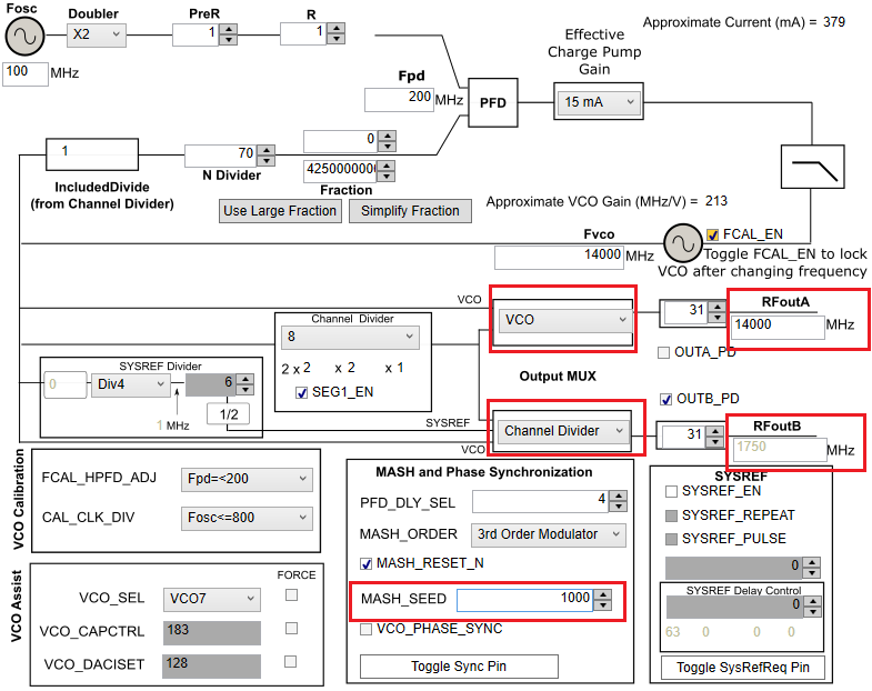
    Yes, we can use MASHSEED to adjust the output phase w.r.t to the reference clock.

    Yes, both outputs can have different output frequencies with different output MUX settings.

  • Is there is commercial, non-space version of the lmx 2615 so we can run some tests in the lab.

    the current evm is very expensive 

  • Hello Rajan,

    You can either test the LMX2694-EP or the LMX2594. The LMX2694-EP is more similar to the LMX2615-SP than the LMX2594. I wouldn't call these commercial versions of the LMX2615-SP as they do have different features and very slight differences in phase noise/power.

    Thanks,

    Vibhu

  • Is the +6/+7 dBm output power from the LMX2615 single-ended or differential?

    Will the above output power remain constant as a function of output frequency

    Can you also confirm that the output from the LMX2615 is a sinewave please?

    Thank you and kind regards,

    Rajan.

  • Can I preset the outputs of the LMX2615 to have different output power levels?

    What are the min/max ranges for the output power?

    What is the relationship between the input reference phase noise and the output phase noise?

    Does the LMX2615 perform any jitter cleaning of the input reference? If so, by how much?

    Thank you and kind regards,

    Rajan.

  • Can two LMX2615's be connected together to generate four phase-locked (coherent) outputs?

    Thank you and kind regards,

    Rajan.

  • Hello Rajan,

    The "OUTPUT CHARACTERISTICS" section of the datasheet specifies the test condition the power measurement was taken under.

    "Figure 17. CHANGE in Output Power vs Temperature" illustrates change in output power over frequency and temperature.

    Output is sinewave format.

    OUTA_PWR and OUTB_PWR registers control the power setting for each output individually.

    We do not specify a min and max power, this will need to be tested for your specific frequency. "Figure 17. CHANGE in Output Power vs Temperature" and "Figure 18. Impact of OUTx_PWR on Output Power" will be useful resources.

    The output phase noise can be modelled on PLLATINUMSIM-SW and the input phase noise can be entered. Typically the lower frequency offsets of phase noise are influenced most by the input phase noise, the middle frequency offsets are influenced most by the PLL and VCO performance and then the far out phase noise / noise floor is dependent on the noise floor of the input as well as the PLL.

    The LMX2615-SP is not a jitter cleaner. Please take a look at our LMK04xxx series. That said not all the noise from the input will be transferred over. Quantifying how much isn't easy and varies from input to input and configuration to configuration. PLLATINUMSIM-SW is your friend!

    Please refer to "7.3.12 Phase Synchronization" and "Figure 26. Determining the SYNC Category" of the datasheet to understand how to generate phase deterministic outputs from two LMX2615-SPs. The outputs can then be adjusted using the MASH_SEED and "7.3.13 Phase Adjust".

    Thanks,

    Vibhu

  • Figure 16 is the most interesting, would you agree that the differential power from each RF output would be approx +15 dBm (50 ohm) and +25 dBm (1 nH)?

    When would one use the 1 nH option?

  • Hello Rajan,

    I would expect that at the output pins with perfect output impedance matching network. The plot in the datasheet isn't meant to illustrate the power you will get on the EVM. The EVM has long traces that aren't optimized for power. This data is the power we expect at the output if the output impedance (changes with frequency, power setting and board design) is matched accurately with the termination network. For the raw data collected a stub tuner was used to tune the load. The output network of the pull-up resistor or inductor may not match the traces and output impedance as well so if you try to measure the power at the output on the EVM you will not get the same results. The traces have loss and the output impedance will not be matched. The 1 nH inductor was used as an attempt to match the output network better than a 50-ohm pull-up, hence you see the better power.

    Thanks,

    Vibhu

  • Hello,

    Why does the LMX2594 EVM provide one differential and one single-ended output, and bizarrely, the single-ended output is the negative part of output B?

    This makes generating two phase-coherent outputs trickier.

    Kind Regards,

    Rajan.

  • Hello Rajan,

    Both outputs on the LMX2594EVM are identical. They can either be used differentially, or single-ended with the unused output terminated to GND via 50-ohm.

    Thanks,

    Vibhu

  • Hi Vibhu,

    I don't agree with your last response, if you have a look at the EVM photograph, its shows that only the negative output B has been connectorised

    www.ti.com/.../LMX2694EPEVM

  • Hello Rajan,

    Your previous question was about the LMX2594 not the LMX2694 so we were referring to different schematics.

    I do not know the exact reason why this EVM was designed the way it was. If I were to guess, it was to demonstrate how to properly terminate an unused output pin and provide flexibility for customers testing differential outputs as well as single-ended outputs.

    Thanks,

    Vibhu

  • How do the LMX2594 and the LMX2694 differ from the LMX2615?

    Thank you,

    Rajan

  • Hello Rajan,

    Apart from the difference in temperatures they are rated for, there are other differences in radiation, packaging and features that can be found on their product folders. Please take a look at the front page of each of their datasheet to start off, and let me know if you have further questions.

    For purposes of testing phase noise, they should all have similar performance.

    Thanks,

    Vibhu