This thread has been locked.

If you have a related question, please click the "Ask a related question" button in the top right corner. The newly created question will be automatically linked to this question.

LMK61E2EVM: Is the following configuration correct?

Part Number: LMK61E2EVM
Other Parts Discussed in Thread: LMK61E2, LMK01000, LMX2581

Hi,

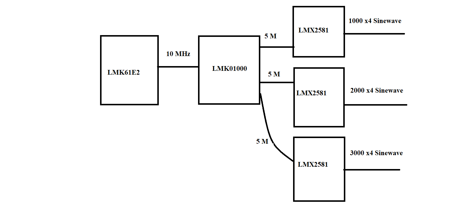
Can you please confirm that the above configuration is valid and can be made using TI parts.

Regards,

Shikhar

  • Hello Shikhar,

    LMK61E2 can generate a 10 MHz that is compatible with LMK01000 input.

    LMK01000 can generate 3x 5 MHz that are compatible with LMX2581 input.

    LMX2581 can generate 2x differential pairs. So you can technically generate 4 single ended sine wave outputs. However, RFoutA+ and RFoutB+ will be in one phase and RFoutA- and RFoutB- will be in the same phase.

    1000 MHz, 2000 MHz, 3000 MHz are all possible.

    Thanks,

    Vibhu

  • Thanks Vibhu.

    I was trying a tunable freq configuration using LMX2581. Is the following configuration correct.

    Thanks

    Shikhar

  • Hello Shikhar,

    Can you confirm that the 500-600 MHz tunable frequency is input from the RFin path.

    If so, yes this is okay. Additionally it would be best to make use of the highest phase detector frequency possible and avoid using a fractional PLL for best phase noise.

    For example taking an input of 200 MHz from a LMK6xxx oscillator would be best to match say a 600 MHz Fin divided by 3 and maximizing the phase detector frequency.

    For most inputs from the first LMX2581 the second LMX2581 can generate a 100 MHz output. There can be cases where there will be a ppb error on the LMX2581. I would say this is negligible.

    Thanks,

    Vibhu

  • Hi Vibhu,

    Thanks for the reply. Understood.

    What if I have the 2 RF outputs (4 pins) of LMX2581 linked as tunable frequency. Say both 500-600 MHz. I require 3 pins for the tunable frequency range. Can I use the last pin to drive the other LMX2581, with a fixed frequency of say 100 MHz, again single output.

    My broad question is can a tunable frequency output/pin of a PLL can be used to drive another PLL? The above case is just an example. It could be possible that the range of tunable frequency is greater than the lock range of the second PLL. In that case can I drive the second PLL?

    Regards,

    Shikhar

  • Hi Vibhu,

    In general what is the rule for a device to drive a PLL or PLL+VCO? The driving frequency first device should just be in the range of the input range of second device? Or you need to be driven by some multiple only?

    Regards,

    Shikhar

  • Hello Shikhar,

    The driving frequency must be in the input frequency range of the second device.

    Typically, regardless of what the input frequency is a fractional PLL can be used to generate the output frequency necessary. In cases where the PLL / PLL+VCO device does not have a fractional N-divider and can only use an integer N divider, the output frequency must be related to the input frequency.

    Input frequency / R divider * N divider = VCO frequency = output frequency

    Input frequency / R divider = Phase detector frequency = VCO frequency / N divider

    If there is an output divider that can be used then the first equation is modified:

    Input frequency / R divider * N divider = VCO frequency = output frequency * output divider

    Input frequency / R divider = Phase detector frequency = VCO frequency / N divider

    In an integer PLL the N divider is an integer.

    Thanks,

    Vibhu

  • Thanks for the reply Vibhu,

    However, I understand the basics of Fractional PLL and Integer PLL. My question was directed more around the tunable frequency case. Sorry, I made it appear extremely broad.

    Consider a VCO in a PLL has a configurable frequency range of 4300-5300. I want to generate a tunable frequency of 430-480 with x spacing. For this I will configure the fractional divider such that the VCO has frequency range of say 4300-4800 with spacing x*10, and I can generate my required output using a 10 divider.

    I get this part. But now, if we have another fractional PLL, say LMX2581 with input range 5-900 MHz and I need to connect it with the above synthesizer. For this should I select divider values that fall in the required range of 5-900. For starters, I know 1-5 divider will not work. However, a divider of 6 from the above synthesizer will work, as it falls in this required range. Is this approach right?

    Regards,

    Shikhar 

  • Hello Shikhar,

    Yes you do need to divide the output of the upstream LMX2581 to a frequency that is acceptable by the downstream LMX2581. Yes, you will need to select divider values that fall in the required range of 5-900 MHz. Your approach is correct.

    Thanks,

    Vibhu