Other Parts Discussed in Thread: PLLATINUMSIM-SW
Hi,
I’m working on the LMX2594, for the sake of shorter lock time, partial assist mode is necessary, and I have some questions about it.
The configuration procedure is as follows (SNAA336):
(The order of configuration is :R8、R7、R6、R5、R4、R3、R2、R1、R0)
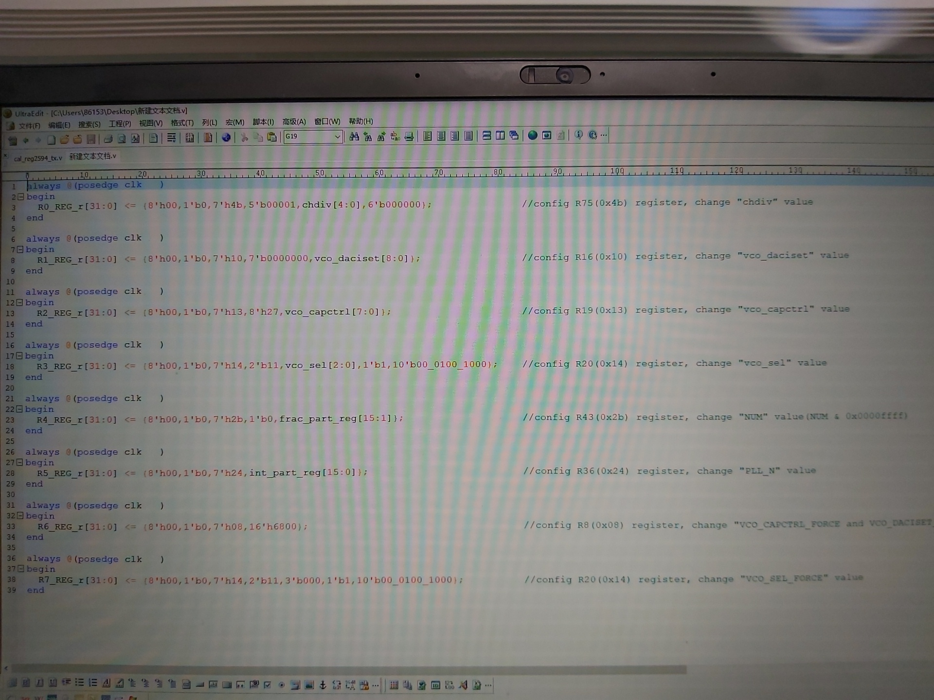
always @(posedge clk )
begin
R0_REG_r[23:0] <= {1'b0,7'h00,16'h251C}; //config R0(0x00) register
end
always @(posedge clk )
begin
R1_REG_r[23:0] <= {1'b0,7'h1f,1'b0,seg1_en,2'b0,12'h3EC}; //config R31(0x1F) register, change "seg1_en" value
end
always @(posedge clk )
begin
R2_REG_r[23:0] <= {1'b0,7'h25,2'b00,pfd_dly_sel,8'h04}; //config R37(0x25) register, change "pfd_dly_sel" value
end
always @(posedge clk )
begin
R3_REG_r[23:0] <= {1'b0,7'h4b,5'b00001,chdiv[4:0],6'b000000}; //config R75(0x4b) register, change "chdiv" value
end
always @(posedge clk )
begin
R4_REG_r[23:0] <= {1'b0,7'h11,7'b0000000,daciset_strt_actual[8:0]}; //config R17(0x11) register, change "vco_daciset_strt" value
end
always @(posedge clk )
begin
R5_REG_r[23:0] <= {1'b0,7'h4e,7'b0000000,capctrl_strt_actual[7:0],1'b0}; //config R78(0x4e) register, change "vco_capctrl_strt" value
end
always @(posedge clk )
begin
R6_REG_r[23:0] <= {1'b0,7'h14,2'b11,vco_sel_actual[2:0],11'b000_0100_1000}; //config R20(0x14) register, change "vco_sel" value
end
always @(posedge clk )
begin
R7_REG_r[23:0] <= {1'b0,7'h2b,1'b0,frac_part_reg[15:1]}; //config R43(0x2b) register, change "NUM" value(NUM & 0x0000ffff)
end
always @(posedge clk )
begin
R8_REG_r[23:0] <= {1'b0,7'h24,int_part_reg[15:0]}; //config R36(0x24) register, change "PLL_N" value
end
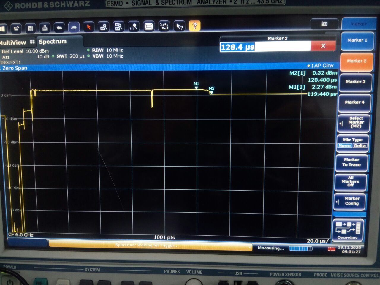
The lock time tested as show in the table:
test condition:
(1). trigger: LE falling edge
(2). equipment: frequency analyser
(3). unit: us
(4). fosc: 200MHz
(5). ACAL_CMP_DLY: 20
(6): CAL_CLK_DIV: 0
(7): BW: 375kHz
(8): SPI Programming Speed: 15.625MHz
(9): Fpd: 200MHz
| LMX2594 partial assist, fosc=200M,ACAL_CMP_DLY=20 | |||||||||||||
| 610MHz | 1010MHz | 1510MHz | 2010MHz | 2510MHz | 3010MHz | 3510MHz | 4010MHz | 4510MHz | 5010MHz | 5510MHz | 6010MHz | 6290MHz | |
| 6300MHz | 80 | 66.8 | 120 | 67.2 | 100 | 66 | 68.4 | 67.4 | 127 | 112 | 106 | 71 | 64 |
| 6000MHz | 84.6 | 84 | 85 | 82 | 84 | 81 | 87 | 85 | 84 | 81 | 80 | 81.2 | 80 |
| 5000MHz | 36 | 35 | 38 | 38 | 41 | 33 | 38 | 38 | 36 | 38 | 41 | 36 | 41 |
| 4000MHz | 61 | 48.5 | 84 | 57 | 64 | 46 | 56.5 | 55 | 91 | 74 | 50 | 60 | 46 |
| 3000MHz | 88 | 83 | 86 | 82.4 | 86 | 78 | 86 | 83 | 91 | 84 | 82 | 78 | 78 |
| 2000MHz | 65 | 76 | 68 | 78 | 70 | 60 | 68 | 56 | 65 | 58.5 | 70 | 67 | 59 |
| 1000MHz | 65 | 54 | 93 | 75 | 75 | 68 | 58 | 65 | 65 | 56 | 85 | 63 | 62 |
| 610MHz | 42 | 42 | 42 | 42 | 42 | 42 | 42 | 73 | 43 | 42 | 43 | 43 | |
Here comes the questions.
(1). Is there any improvement with the configuration procedure? Please inform us.
(2). Is the lock time showing in the table the shotest one?
Thanks for advance.
Feifei Zhang.