This thread has been locked.

If you have a related question, please click the "Ask a related question" button in the top right corner. The newly created question will be automatically linked to this question.

LMK04828: When the temperature drops, PLL1 of LMK04828B loses its lock

Part Number: LMK04828
Other Parts Discussed in Thread: TIDA-010122, , PLLATINUMSIM-SW

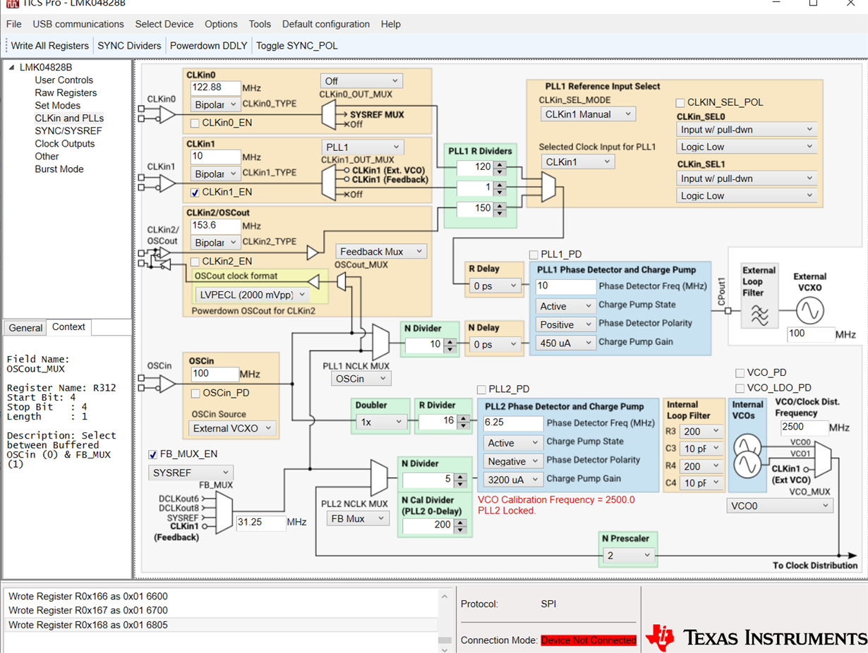
LMK04828B configuration as follows:
Hardware design refer to TIDA-010122
10MHz input Clkin1, Dual-PLL mode, output frequency: 31.25MHz, 125MHz, 250MHz
Feedback Mux = SYSREF = 31.25MHz
We manufacture up to 15 Boards. Most of them (not all) have the following phenomena:
After power these boards, we use a small fan to cool them, the lock-detect led of PLL1 and PLL2 will turn on and remain unchanged. But when we try to use a more powerful fan to cool them (focus on LMK04828B), the lock-detect led of PLL1 will blink and PLL2 lock led will not blink. Then we change to small fan, the PLL1 lock led will gradually keep the lights on.
All these board had been immersed in electron fluoride liquid of 3M.

Obviously, temperature can affect PLL1 locking. Can anyone give me some help? Thanks!

  • Hi user4404342,

    Do you know the actual device temperature? Or at least a reasonable approximation? I want to ensure the device is within the operating temperature range. We have characterized PLL1 lock tolerance from -40°C to 85°C, and this range is reliably guaranteed for normal operation - I suspect the issue is not with the LMK04828 temperature, unless you are operating outside of the characterized range. 

    The immersion substance you're describing is some kind of Fluorinert, right? I don't know the specifics of your cooling solution, but is it possible that there is some mechanical vibration being coupled into PLL1 or the VCXO due to the large fan and volume of fluid?

    If you have access to OSCout (CLKin2), it may be helpful to observe the phase noise, or at least check for pulse consistency on the VCXO with an oscilloscope, when using the different fan sizes. Alternately, you could use the status pins to mirror the PLL1 R/N divider outputs. If you see large close-in phase error, or spurs at multiples of the fan frequency, this would suggest mechanical vibration as a potential root cause. You could also try increasing the loop bandwidth of PLL1 to track out issues with vibration sensitivity, although this would likely increase the close-in phase noise of all the LMK04828 clocks.

    Regards,

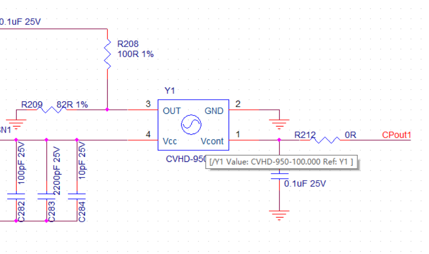
  • The LMK04828B device tempreture is about 60~70℃(small Fan), and below 40℃(large cool FAN). The device is within the operating temperature range. The VCXO is CVHD-950X-100.0000. 

    The immersion substance is FC-40(extcon.co.uk/.../versions.pdf) of 3M™ Fluorinert™ Liquids. Liquid will circulating flow. Now I will share some more info: those boards which have problem after they are soaked in FC-40, and those boards have no problem before soaking in FC-40.

    Thanks for your replay!

  • I do some more test on CPout1.

    Cpout1 of the normal board is 2.208V when PLL1 is lock. Then we use a 17-degree air conditioner to cool it for half of hour, It is still locked and the Cpout1 is 2.39V.

    Cpout1 of the abnormal board is 2.56V when PLL1 is lock. Then we use a 17-degree air conditioner to cool it for only ten seconds, It is un-locked and the Cpout1 is 3.258V.

    It seems that the abnormal board's Cpout will easily reach to CPout1's Max value for temperature sensibility. The season point to VCXO.

  • Hi user4404342,

    Thanks for confirming the operating temperature, that looks to be within the rated range for the VCXO and the LMK04828. 

    The CVHD-950X-100 is an open-frame VCXO, so Fluorinert is definitely getting into and around the oscillator and tuning circuitry. I wonder if the difference in dielectric coefficient is impacting the capacitance at the crystal oscillator pins. Perhaps there is some relationship between dielectric coefficient and temperature in the Fluorinert which causes enough capacitance change to knock the VCXO off-frequency as the system is cooled.

    To test this, you could tri-state the charge pump on PLL1 (PLL1_CP_TRI=1), apply a constant DC voltage to CPout1 (can be external, or from LMK04828 with HOLDOVER_FORCE=1, MAN_DAC_EN=1, and MAN_DAC=floor((Vtarget/3.3V)*1023), see datasheet 9.3.7.1.1), and observe the change in VCXO frequency (or output frequency of any PLL2 output if PLL2 remains locked, as ppm error should track through the PLL) as you add Fluorinert and change system temperature. If the VCXO is being pulled beyond the specified tuning sensitivity limit with a constant DC voltage value, this suggests that the CVHD-950X-100 is not suitable for use with Fluorinert.

    Another possible test: you could swap the VCXO on an unsubmerged board with a different VCXO that has a hermetically sealed package, and try the test again. The hermetically sealed package should ensure the crystal capacitance remains unchanged even when the device is submerged; if PLL1 remains locked with the hermetically sealed VCXO, this also points to incompatibility with CVHD-950X and Fluorinert. I caution against swapping out the VCXO or other components on the submerged board unless you are sure you can do so safely, because soldering temperatures will vaporize the Fluorinert trapped within or beneath the VCXO.

    Regards,

  • Hello:

          Thank you. I will do first one test as you descibed. I want to make it a little bit clearer :  the abnormal board had been soaked in Fluorinated and then we take it out.,Then we test it in the air.

          Today I found that if I only change the charge pump gain(R0x15B) of PLL1 from 450uA to 1550uA on abnormal board, the PLL1 would be more stable or say not easy to lose lock. For 450uA, I only cool  the board ten seconds and PLL1 loss it's lock; For 1550uA, I cool the same board about 4 minutes and then PLL1 loss it's lock.


          I use one of PLL2 out (250MHz) to generate a periodic pulse by FPGA, then use pulse as the trigger source of oscilloscope to observe the inpiut clock 10MHz. When using air conditioner to cool the abnormal board , I can see that the fixed phase between 10MHz and pulse disappeared. Then close the air conditioner for a moment, the fixed phase between 10MHz and pulse reappear.

  • HELLO:

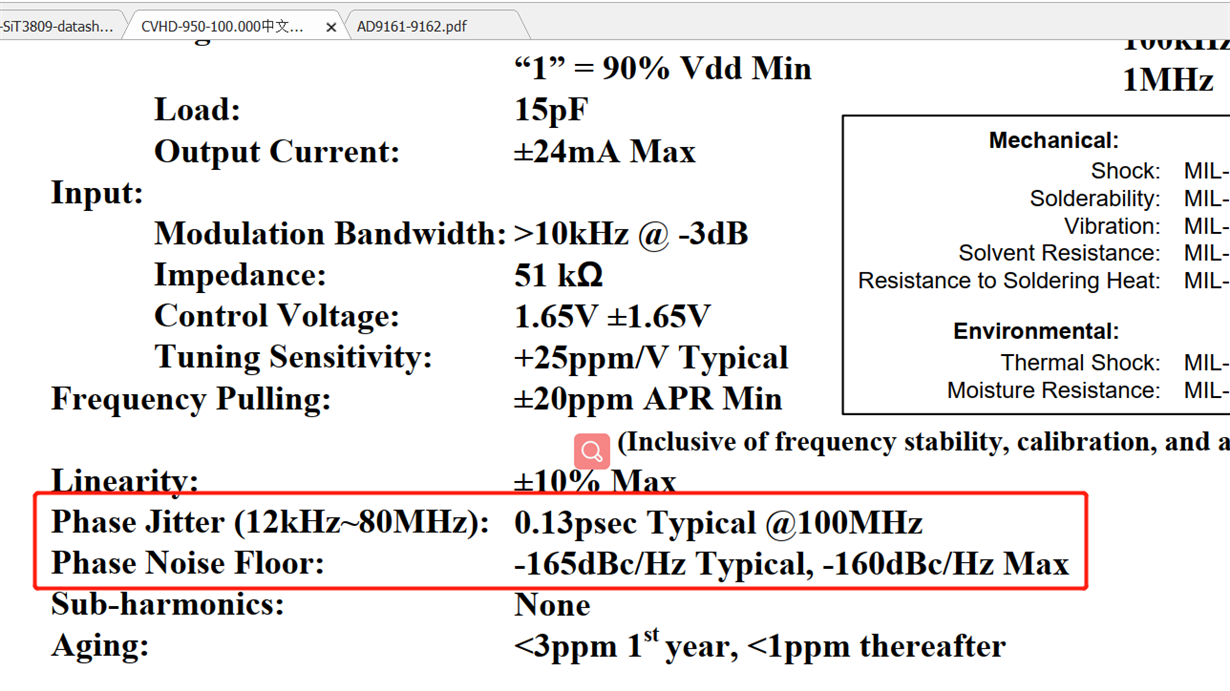
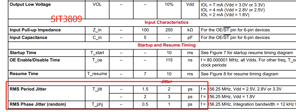
              Recently I change the CVHD-950X-100.00000 to SiT3809AI-2F-33NB-100.00000 (Industrial, -40 to 85ºC, Frequency Stability = ±10ppm, 3.3V, Pull Range = ±50ppm, 100MHz). When I tested the board in the air, the PLL1 lock-detect LED will blink quickly. I compare these two VCXO. Can it be due to the jitter performance is diiferent?

    SIT3809

    CVHD-950X-100.0000

  • Hi user4404342,

    First, your images didn't load properly, could you please reupload if they're critical to the discussion?

    Second, even if the jitter is higher, this should not prevent PLL1 from locking. The PLL1 lock detect mechanism indicates loss of lock when the difference between the phase detector input edges is greater than several nanoseconds, whereas the jitter is three orders of magnitude lower. Also, the pull range is similar, so the oscillator gain should also be similar; if the loop filter settings were sufficient for CVHD-950 to lock, they should also be sufficient for the SiT3809.

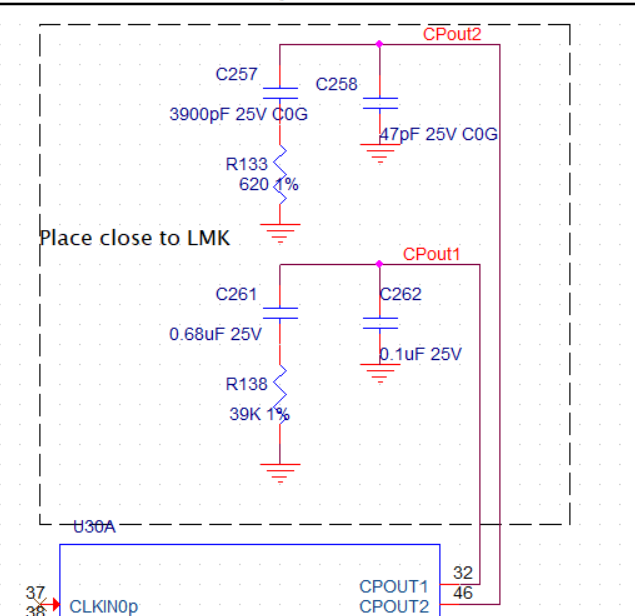
    Maybe there is an issue with the loop stability. Are you using the same loop filter settings as TIDA-010122 (C1 = 0.1µF at CPout1 + 0.1µF at Vtune pin of VCXO; C2 = 680nF, R2 = 39kΩ)? What charge pump gain and phase detector frequency are you using for PLL1?

    Regards,

  • LMK04828 configuration: charge pump gain=450uA, PDF=10MHz

    PLL filter and VCXO:

    CVHD-950X Phase Jitter:

    SIT3809:

  • Hi user4404342,

    Thanks for sharing the settings. I checked using PLLatinum Sim (PLLATINUMSIM-SW) and found that your PLL1 phase margin is about 10°, so the loop is not very stable - and this is probably responsible for the issues with locking the PLL. That bandwidth was originally implemented on the LMK04828 EVM with a 122.88MHz VCXO and expecting a 10MHz reference, for which the highest usable phase detector frequency is 80kHz; at 10MHz, the loop transfer function changes substantially, and the loop filter components should be updated to match. Additionally, the equivalent to C417 was populated with 100pF to help reduce the impact of ground-referred noise at the control pin, but somehow the reference design appears to have populated 100nF instead.

    If you want a stable loop at 100Hz bandwidth, 10MHz phase detector, I recommend:

    • C262 = 22nF
    • C261 = 1µF
    • R138 = 5.6kΩ
    • C417 = DNP

    I also checked to see if there were any software-only changes that could be made to stabilize the PLL1 loop with the components present on the board, but I found nothing above 40° (ideally should be >= 50° to provide margin against changes in component value across temperature). If you would like to optimize your loop filter component selection beyond my suggestions, you can download and test the LMK04828 PLL1 in PLLatinum Sim.

    Please let me know if you continue having trouble after changing the loop filter, and we can continue investigating.

    Regards,

  • Hi Derek Payne,

        Thank you very much! I will have a try!

  • Hello,

          I have tested the board but PLL1 lock is still blink. Configuration as follow:

    • C262 = 18nF
    • C261 = 1µF
    • R138 = 5.9kΩ
    • C417 = DNP

  • Hi user4404342,

    What kind of input reference are you using? CLKin1 on TIDA-010122 is connected to an external port, so if you are using a low slew-rate source like a sinewave signal generator to generate the 10MHz, that could be the issue. The minimum input slew rate for CLKin1 is 0.15V/ns, and sine wave slew rate is given by SR = 2π*f*Vpk; for a 50Ω, 10MHz sine wave, this comes out to about 12dBm differential or around 15dBm single-ended as the minimum input power. Of course, if your 10MHz reference is from a high slew-rate source such as a CMOS output, the input slew rate is likely not the limiting factor.

    Regards,