This thread has been locked.

If you have a related question, please click the "Ask a related question" button in the top right corner. The newly created question will be automatically linked to this question.

LMX2820: high phase noise issue

Part Number: LMX2820
Other Parts Discussed in Thread: LMX2594

We've been having some issues with phase noise that is higher than the simulated output, we have narrowed down the source to the LMX2820. As a test we put in a 10 MHz CMOS output crystal and configured the device to output 6 GHz. The 10 MHz reference has the following phase noise specifications:

100 Hz                -123 dBc/Hz                             
1000 Hz              -142 dBc/Hz
10000 Hz            -149 dBc/Hz
100000 Hz          -150 dBc/Hz
1000000 Hz        -150 dBc/Hz
10000000 Hz      -150 dBc/Hz

In the PLLatinum simulation (with a 2nd order loop filter: C1 3.3nF, C2 47nF, R2 100 Ohm) with an output frequency of 6GHz we get a simulated noise output of:

100 Hz                -67   dBc/Hz                             
1000 Hz              -86   dBc/Hz
10000 Hz            -93   dBc/Hz
100000 Hz          -93   dBc/Hz
1000000 Hz        -119 dBc/Hz
10000000 Hz      -151 dBc/Hz

But when we measure the output we get ~20dB higher numbers in the 1kHz to 100kHz range:

100 Hz                -60 dBc/Hz                             
1000 Hz              -66 dBc/Hz
10000 Hz            -74 dBc/Hz
100000 Hz          -102 dBc/Hz
1000000 Hz        -120 dBc/Hz

I understand that this is not an ideal setup, but this is a test to identify the source of the high phase noise. In the real setup we have a high end 100MHz reference source feeding into a LMX2594 which feeds into the LMX2820. 

Simulated file project (both PLLatinum, and TICS Pro files), reference noise, schematic and measurement data attached for reference.

Phase Noise.zip

  • Hi Marijn,

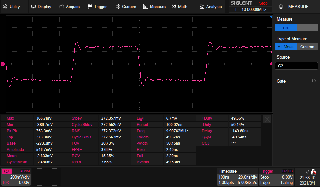
    Could you measure the waveform of the 10MHz clock at OSCIN_P pin? (assuming you have connected this clock to the _P pin).

    As you can see from the simulation, the ultimate phase noise is basically dominated by the phase noise of the reference clock.  The simulation tool, however, is not able to account for the effect of reference clock slew rate. Since there is a 50Ω termination at the input of the OSCIN pins while the clock source is CMOS, I am a bit worry that your clock source is not able to drive 50Ω well and as a result, the slew rate got hurt.

  • Hey Noel,

    This is the signal at the input of the OSCIN_P pin, with OSCIN_N connected to ground through 50 Ohm + capacitor. It's not the fastest edge, but it's not too bad. We also had the same issue with the LMX2594 output feeding into the LMX2820. There we had sub ns rise and fall times.

  • Hi Marijn,

    The waveform looks good.

    I read your data attached in the first post again, I see something outstanding.

    The measured phase noise at 6GHz indicated that the loop bandwidth is around 15kHz but from simulation, it should be 78kHz. Are you sure you have the loop filter modified to the said values?

    Can you try make LMX2594 output equals 100MHz and then in LMX2820, set the R divider to 5 to make its fpd = 20MHz, are you getting the same phase noise as if you are using 10MHz input?

  • Hi Noel,

    I agree that this is indeed very odd. I'm sure the loop filter is correct. When I saw this response that was also the first thing I doubted. So to be sure of that I resoldered the components in case a mistake was made at assembly.

    Just did, and that indeed gives me the same phase noise as having the 10 MHz input.

    If I change the charge pump settings, then I do see the response change and the loop bandwidth getting even smaller. So it does seem to be working in some sense. The decoupling on the all the BIAS, REF and REG lines should be in accordance with the datasheet, although I can't find what bias voltages should be on those pins (not listed in the datasheet, unlike the LMX2594).

    Marijn

  • Hi Marijn,

    So, it is not a input clock slew rate and input clock doubler issue. 

    What happen if you make fpd = 100MHz? will the loop bandwidth recover to 310kHz?

  • Hi Noel,

    No, it stays around 15kHz. Also tried with an fpd of 120 MHz, no difference at all.

  • Hi Marijn,

    So the phase noise plot did not change at all? this is really odd. 

    BTW, are you working on your own board or TI EVM?

  • Hi Noel,

    Indeed, and I really don't understand how this can happen. This is our own PCB, but the schematic is very similar to the EVM. I added a screenshot of it in the zip in my first post.

  • Hi Marijn,

    Your schematic is fine and I assume your software is good as well because you can program the device and make it locked. I can't think of anything else at the moment. Did you see anything suspicious in the layout?

  • Hi Noel,

    Sorry for the long silence on my end, but I finally managed to track down the issue. It turned out to be a wrong value at a reserved part of register R19. If bits 15-5 are not 0x109 (we accidentally set them to zero), the phase noise shoots up and the device also becomes less stable.

    Thanks for all your help and suggestions.