This thread has been locked.

If you have a related question, please click the "Ask a related question" button in the top right corner. The newly created question will be automatically linked to this question.

LMK04832EVM: Can't produce a 156.25 and 125Mhz output clock

Part Number: LMK04832EVM

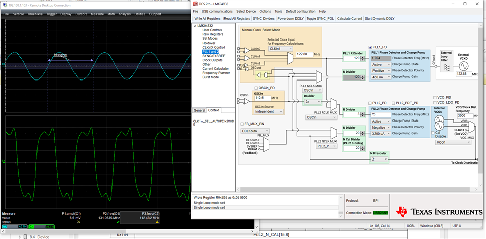
I tried to drive the VCO0 on PLL2 clock to 2500MHz with a 112.5MHz reference clock, but the 156.25 MHz clock after the divider turns out to be 170MHz and the 125MHz clock after the divider turns out to be 136MHz. What is going on here?

  • Hello,

    My coworker will reply in 24 hours.

    Regards,
    Hao

  • Hi Edwin,

    It sounds like the PLL isn't locking. 112.5MHz is not an integer multiple of 2500MHz, the closest phase detector frequency is 12.5MHz; is this what you're using?

    If you are using the standard pre-divider -> N-divider feedback path for PLL2, have you confirmed that PLL2_N_CAL is set the same as PLL2_N? Note that PLL2_N_CAL must be set before the LSB register of PLL2_N to trigger a calibration sequence with the correct N-divider value.

    Regards,

    Derek Payne

  • Hi Derek,

    I changed my output clock to 120MHz and 250MHz with a 112.5MHz reference clock.  I am still seeing the same problems

    Below are my settings on the TICS PRO and the oscope I am capturing on my lmk4832EVM (top is input, bottom is output


    I am also not sure if I am using the TICS PRO correctly as well.  I just click on the write all of the registers at least twice wishing that would do all the PLL calibrations.

    Thanks,

    Edwin

  • Edwin,

    From what I can see of the PLL page, the configuration looks to be set up correctly. Would it be possible for you to share your TICS Pro save file? File -> Save produces a .tcs file which stores all of the register settings and all system frequencies. E2E Insert -> Image/Video/File menu option can upload the .tcs file.

    Did you modify the loop filters at all? Even with default EVM loop filter settings, I calculate that your configuration should be stable.

    Do you have a schematic section showing how the OSCin is connected?

    I don't see the amplitude of the signal in your screenshot, but can you confirm that it's greater than -3dBm? Sine wave slew rate is 2pi*F*Vpk, so to meet the minimum slew rate requirement of 0.15V/ns you must have 2pi*112.5MHz*212mVpk, with 212mVpk corresponding to just less than -3dBm. Ideally the amplitude should be much higher, more like 6dBm.

    Regards,

    Derek Payne