This thread has been locked.

If you have a related question, please click the "Ask a related question" button in the top right corner. The newly created question will be automatically linked to this question.

TPL5111: Some parts draw way too much current

Part Number: TPL5111

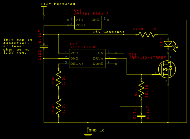
I have a PCB in production which uses a TPL5111 to flash an LED about every 2.5 seconds.  Each flash is about 5mS long and the LED uses about 13mA during that time, so the average current draw due to the LED is about 26uA.  The AP7381-50SA-7 voltage regulator has a quiescent current of about 2.4uA.  The typical current draw of the TPL5111 at 0.035uA is insignificant.  Most PCBs with this circuit pull about 30uA, which gives good battery life.  Unfortunately, I discovered that some TPL5111 chips draw far more current, from 1200uA to over 4000uA, which reduces the battery life by 100x or so.  I'm sure it is the timer chip that is the problem, based on the problem following the chip when I swap them between boards.

I have three boards built in early 2020 which work as expected, and 18 recent boards which are also OK.  I have five sample boards from various PCB batches from the timeframe in between, of which four draw too much current (1200uA, 1200uA, 2230uA and 4000uA).  All of the chips are marked ZFVX on top.  I pulled a few chips off of the boards to check the marking on the bottom.  So far the ones marked 84H have all been good.  Of those marked 87N, two have been bad and one good.

I'll be able to test a new batch of PCBs soon and can provide more test results then, but in the meantime I would be interested in any suggestions about what the cause might be, things I should test, problems in the design, or anything else which might lead to identifying the cause.

If the schematic below isn't visible, it can also be found here.

Thanks,

Steve

  • In case it wasn't clear, the high current draw with the bad timer chips occurs _between_ the LED pulses; it isn't just that the current draw is enough higher during the pulse to raise the average.  In other words, rather than using about 2.4uA between pulses, it uses 1200uA or more.

  • Hi Steve,

    Thanks for bringing this to our attention. This issue has not been reported before and its not yet clear what the cause is.

    Are you observing any other functional issues with the device, or is the device behaving properly and only the current consumption is the only issue?

    You could confirm the supply voltage and time interval are meeting the expectation. Is the LED behavior different for the faulty devices?

    I don't see any glaring issues with the design.

    Kind regards,
    Lane

  • We have not observed any functional issues in the 700 or so we have used.  The LED blinks just fine on all of them.

    The PCB is supplied from a 12V battery.  The 5V regulator used to power the timer and LED is not used for anything else.  On the six boards I  still have handy to test (including all of the ones that drew too much current), that regulator's output varies from 4.93 to 5.01V steady state, with a little 10mS long dip of about 800mV each time the LED blinks.  Following that dip the voltage overshoots the steady state by about 160mV.  Still nothing close to the 5.5V recommended max supply voltage and miles from the 6.0V absolute max.  Initial power up is clean, with no overshoot.  One prototype board has a 3.3V rather than 5V regulator and works fine (with low current draw).

    Within the next couple of weeks I should have 125 boards from each of two manufacturers that I can test, so we'll have more info then.  In the meantime, I would be glad to send chips that draw too much current for analysis, and if I can eventually get them back, I could send a couple of PCBs, one with the problem and one without.  

    Thanks,

    Steve

  • Hello Steve,

    What happens if you disconnect the LED, then power up the board such that there is no large voltage delta?  Is a current still high?

    73,
    Timothy