This thread has been locked.

If you have a related question, please click the "Ask a related question" button in the top right corner. The newly created question will be automatically linked to this question.

LMK04832: How to configure lmk04832 to support sine wave clock source input

Part Number: LMK04832

Hi  team:

I am using lmk04832 for board clock solution. The CLKIN0 can switch to support 10MHz osc and sine wave clock source.

1) When using the 10MHz osc, lmk04832 can work okay;

2) When switch to 10MHz sine wave source, the pll1 can not locked;

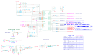
The schematic and tics project files is attached.

Please help figure out the root cause. Many thanks!

 VP101B_LMK_INIT_EXT_10M_SINEWAVE.tcs

  • Hello Bo,

    Sine wave slew rate at 10MHz is below the minimum recommended operating conditions. Sine wave slew rate is given by SR = 2π*f*Vpk. For 10MHz sine wave to meet the datasheet minimum slew rate of 0.15V/ns, Vpk = 0.15V/ns / (2π*10MHz) = 2.39Vpk, or around 4.8Vpp. The shaded area of the chart below graphically renders the input slew rate requirement against the maximum single-ended input swing for CLKin inputs; below 20MHz, it is not possible to supply a pure sine wave single-ended to achieve the minimum recommended slew rate. 

    A few other things:

    • You may be able to at least get the device to lock by supplying the 10MHz signal at around 11.5dBm (maximum single-ended input power which conforms to allowed single-ended voltage limits). It may perform worse than the datasheet values due to operating outside of the recommended slew rate range, but it might be sufficient for testing or just getting lock.
    • If you can clip the sine wave to the required input range limits with minimal distortion, you could increase the power and the slew rate without exceeding the input voltage limit.

    Regards,

    Derek Payne