This thread has been locked.

If you have a related question, please click the "Ask a related question" button in the top right corner. The newly created question will be automatically linked to this question.

TLC555-Q1: TLC555-Q1, max freq, tolerance

Part Number: TLC555-Q1

Hi~

Customer is under investigating to minimize TLC555-Q1 PWM generator tolerance.

Would you please check below item?

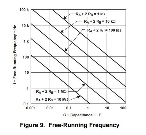
1) Max frequency which can set TLC555-Q1

2) In datasheet, initial error is max 3% under 25deg, how about -40~105deg? can we get that data?

Thanks.

  • Hello,

    The initial error of timing interval at 3% is under a very specific set of test conditions. Specifically at 4.8kHz and 480hz test conditions. We do not have data for other temperatures. 

    To minimize errors the customer would operate at frequencies under 100kHz as shown in the Free-Running Frequency plot below. Frequencies beyond 100kHz become more difficult to get good accuracy due to propagation delays starting to play a role. The curve becomes non-linear beyond 100kHz. In order to operate at higher frequencies board parasitic capacitance plays a role. When the timing capacitor is small, board parasitic capacitance may start to play a role and should be accounted for. 

    There are some general best practice guidelines to follow for minimizing parasitic capacitance in the layout of the PCB.

    1. Increasing space between adjacent traces
    2. Cutting out power and ground planes above and below critical traces
    3. Minimizing component to component trace lengths. Shorter traces will have less capacitance due to capacitance per unit length.
    4. Minimizing use of Vias on critical traces.

    In addition the propagation delays depend on the supply voltage and should also be accounted for as shown below: