This thread has been locked.

If you have a related question, please click the "Ask a related question" button in the top right corner. The newly created question will be automatically linked to this question.

LMK04610: LMK04610 accuracy in switching inputs

Part Number: LMK04610

Hello everyone.

I have correctly configured LMK04610 IC. It has on its two inputs 40MHz from KEYSIGHT 33600A double channel generator. I also used VCXO

ABLNO-V-122.880MHz. Output frequency on nr 5 output is about 10MHz (its convenient to measure), but in a future I will change it to 200MHz.

LMK04610 also correct work on missing first or second input clock. It swich to holdover mode for about 1,5 period of PFD frequency (in my case 80kHz - about 15us)

hold Vcontrol voltage at correct value and swich signal to another source.

And after select another input signal the problem begins. I will just add, that the same situation occurs when resetting the N and R dividers - when I set

PLL1_RDIV_SWRST and PLL1_NDIV_SWRST bits (3 and 4) in 0x57 configuration register.

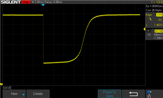
The problem is that PLL1 misses a few clock signals, which can be seen on the control voltage oscillogram. I have attached two oscilloscope screenshots.

As you can see VCO regulation is only on one direction. So VCO phase only change on one side. The integrated control voltage corresponds to a phase change 100ns (it is slightly change when I set another loop parameters). This value corresponds to about 12 clk of 122.88MHz or 4 clk input frequency 40MHz.

My question is that is normal situation? Is any way to initially set R or N divider instead reset? (after holdover R and N dividers are also reset) Is there any other possibility that we could minimalize observed behaviour?

  LMK04610_10MHz_out.tcs


  • Hi Piotr,

    we will look into this and get back later, stay tuned.

  • Thanks for the quick reply.

    I will just add that the graphs relate to the loop parameters of 12Hz prop_final = prop_fast = 4 and 120Hz prop_final = prop_fast = 40, respectively, both in 50% mode.

    When the mode is changed to low pulse mode (LPM), the loop has trouble to lock and its final gain is weak, what correspond to low stability of output clock. But in LPM the switching input is more slight because I don’t observe so huge Vcontrol overregulation.

     
  • Hi Piotr,

    will check over the weekend.

  • Hello Piotr,

    Do I understand it does lock, but you are trying to minimize the phase/frequency hit during switch?

    Do you have a frequency or phase spec you are trying to achieve?

    73,
    Timothy

  • Exactly. I trying to minimize the phase/frequency hit during switching inputs. I want to achieve the lowest possible frequency deviation during switching. I think that 1 CLK of input will be acceptable. LMK04610 in HMP and 50% mode lock normally after power on, but in LPM I have to many times on/off input signal and after few attempts PLL is locked.  As I wrote earlier in LPM  final gain is weak but voltage overregulation at switching is many times smaller.   Maybe the solution is a better VCXO with lower tuning sensitivity (kHz / V) and better "long-term" stability and use of LPM mode?

  • Hi Piotr,

    LPM of this part will reduce the influence of the proportional gain as the prop charge pump is only active during the high pulse of the PFD output. Using LPM, the effect of the proportional is reduced which results in a reduced PLL bandwidth. The lower bandwidth results in smaller effects when doing a switch over.

    Based on your config, when selecting LPM, the loop peaks a bit and shows a bandwidth of 0.44Hz. This peaking will cause your problems with locking. Therefore you would need to adjust prop gain.

    You can try out proportional gain of 20 to 40. 20 will still show some peaking, but much smaller vs prop=4. Loop bandwidth is then ~0.52Hz. With prop=40 you reduce the peaking even further which should give you a more stable lock, but bandwidth is higher at ~0.74Hz.

    You will need to find tune the prop value to get an optimal solution for locking and switching performance.

    this app note describes the PLL in detail: https://www.ti.com/lit/an/snaa310/snaa310.pdf

    Let me know if that helps.

    regards,

    Julian