This thread has been locked.

If you have a related question, please click the "Ask a related question" button in the top right corner. The newly created question will be automatically linked to this question.

LMK05028EVM: DPLL Phase Lock Detectors setting

Part Number: LMK05028EVM
Other Parts Discussed in Thread: LMK05028

Hi,

Let me ask you some questions about DPLL Phase Lock Detectors setting.

My customer has been evaluating LMK05028EVM with TICS Pro.

The customer would like to make 2 clocks from OUT7 and OUT6 by using IN0 and IN1 input.

But the output becomes following, because "loss-of-phase lock"(LOPC) is detected and then device becomes "HOLDOVER" condition.

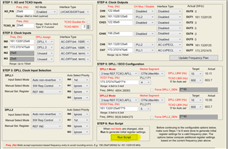
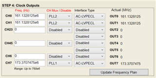
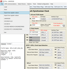
 IN0 : 161.1328125MHz ---> DPLL1 ---> OUT7 : 173.3707475MHz

 IN1 : 173.3707475MHz ---> DPLL2 ---> OUT6 : 161.1328125MHz

The questions are as follows.

Q1) Setting values 

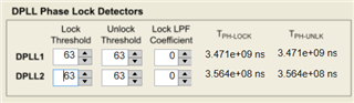
The setting values of "DPLL Phase Lock Detectors" are as below.

Are these correct?

If not, please tell me the right one.

 DPLL1 : Tph-lock --- 12.93ns  Tph-unlk --- 51.73ns

 DPLL2 : Tph-lock --- 10.62ns  Tph-unlk --- 42.49ns

Q2) If possible, will you tell me how to disable "DPLL Phase Lock Detectors" ?

I attached "setting file" of TICS Pro for your reference.

Thank you for your support.

Best Regards,

Takumicdr_210802_mask3.tcs

  • I would like to correct my latest post as below.

     >My customer has been evaluating LMK05028EVM with TICS Pro.

    ---> My customer has been evaluating LMK05028 on their own trial board.

          TICS Pro is used to make/confirm the register values.

    Thanks and Best Regards,

    Takumi

  • Hello Takumi,

    1. After filling out the appropriate values in steps 1 to 5 in the image shown below, press run script in step 6. Performing the run script will automatically generate the optimal DPLL phase lock detector values.

    2. It is not possible to disable the DPLL phase lock detector. The threshold values can all be set to 63 (its max value) so that the phase lock status will be shown as locked if the phase difference is up to 3 seconds. Please note this is not recommended.

    Regards,

    Kia Rahbar

  • Hello Kia-san,

    Let me confirm the contents of your answer about my question1.

    I tried to do your instruction about TICS Pro without connecting LMK05028.

    The result is as below.

    Is this result correct?

    The result is,

     DPLL1 : lock 35ns, unlock 37ns

     DPLL2 : lock 38ns, unlock 40ns

    And seems to be error message "Run cancelled. OUT[4:7] bank needs 1+clock from PLL1, OUT[0:3] bank needs 1+clock from PLL2"

    is appeared on the left-down side of the field.

    Is this normal situation?

    Sorry for my basic question.

    Regards,

    Takumi

  • Kia-san,

    Thank you for your support.

    Let me ask you an additional question as below?

    The question is about "Register setting sequence".

    Now the customer is setting the registers from "small number register to large number register" once at power on reset.

    Is this sequence correct?

    If not, will you tell me the right sequence, please?

    Regards,

    Takumi

  • Hi Kia-san,

    My customer tried to do your proposal about "threshold values set to 63".

    The result was, the situation was not changed,

    "LOPL was detected and the condition was HOLDOVER", to my regret.

    And, can I ask you 2 more questions as below,please?

        - Under the condition that bit2-0 shows "0" of register R14/15,

          is there any possibility the device becomes "HOLDOVER" by "REF is not normal"?

        - Is there any possibility the device becomes "HOLDOVER" without detecting "LOR"

          in case input clock is not stable in the term from power on reset to register settings?

     Sorry for my many questions but I appreciate your support.

    Best Regards,

    Takumi

  • Hello Takumi,

    1. Please try moving the 161.1328125 MHz output from OUT6 to OUT0 (as shown below) and then re run the run script to determine the optimal DPLL phase lock detector values. It is recommended to have all the PLL2 clocks come from the OUT[0:3] bank and all the PLL1 clocks come from the OUT[4:7] bank.

    2. Yes, registers should be set from small number register to large number register.

    3. After programming all the registers, can you please attempt a "soft-reset Chip". This could fix the holdover issue.

    Regards,

    Kia Rahbar

  • Hello Kia-san,

    Thank you very much for your reply.

    But I do not understand well what your instruction.

    Because the customer does not use TICS Pro as debug tool for their board.

    That is to say, they are using TICS Pro as only tool to check register setting and they do not connect TICS Pro to their board.

    My understanding is, TICS Pro does not work without connecting the device...Is this correct?

    So about your answer 1, I suppose that we do not get "optimal DPLL phase lock detector values" by TICS Pro without connecting the device.

    If my understanding is not correct, please tell me that?

    Thanks so much for your kindness support.

    Best Regards,

    Takumi

  • Hello Takumi,

    Yes, a device must be connected to TICS Pro for it to work.

    I am recommending you try obtaining the correct configuration through TICS Pro as it is easier to observe the issue you are facing.

    Please use your LMK05028EVM and TICS Pro to preform the actions I have described above. Once we have the device locking through TICS Pro, you can export the hex register values and use them to program your LMK05028 device on your trial board.

    The hex register values can be exported as shown below:

    Regards,

    Kia Rahbar

  • Hi Kia-san,

    Thank you for your reply!

    I understood well.

    Regards,

    Takumi