Other Parts Discussed in Thread: LMX2594
Please give me some advice regarding the phase noise of the LMX2594.
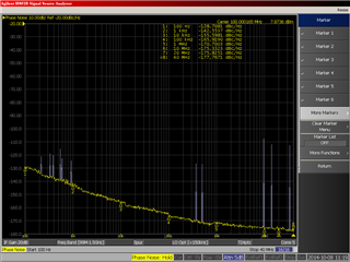
Figure 1, there is a difference between the measured value at 100kHz and the simulation.
What could be the factors that cause these characteristics?
The following materials for consideration are attached.
What else do you need?
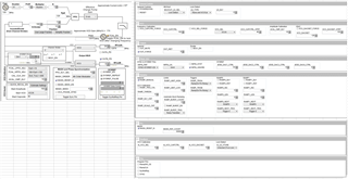
Figure 2 shows the simulation settings.
Figure 3 shows 120MHz Fosc phase noise (SG: Keysight E4433B).
Figure 4 shows the TICS Pro settings(Raw Registers).
Regards,
Akihiko Yokouchi/
Fig 1
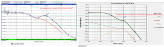
Fig 2
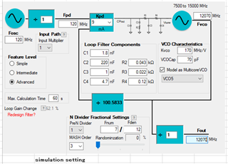
Fig 3
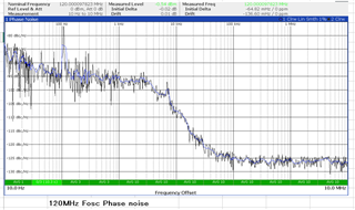
Fig 4
Raw Registers
R112 0x700000
R111 0x6F0000
R110 0x6E0000
R109 0x6D0000
R108 0x6C0000
R107 0x6B0000
R106 0x6A0000
R105 0x690021
R104 0x680000
R103 0x670000
R102 0x660000
R101 0x650001
R100 0x640000
R99 0x630000
R98 0x620000
R97 0x610888
R96 0x600000
R95 0x5F0000
R94 0x5E0000
R93 0x5D0000
R92 0x5C0000
R91 0x5B0000
R90 0x5A0000
R89 0x590000
R88 0x580000
R87 0x570000
R86 0x560000
R85 0x550000
R84 0x540000
R83 0x530000
R82 0x520000
R81 0x510000
R80 0x500000
R79 0x4F0000
R78 0x4E005D
R77 0x4D0000
R76 0x4C000C
R75 0x4B0800
R74 0x4A0000
R73 0x49003F
R72 0x480000
R71 0x470021
R70 0x46C350
R69 0x450000
R68 0x4403E8
R67 0x430000
R66 0x4201F4
R65 0x410000
R64 0x401388
R63 0x3F0000
R62 0x3E0322
R61 0x3D00A8
R60 0x3C0000
R59 0x3B0001
R58 0x3A8001
R57 0x390020
R56 0x380000
R55 0x370000
R54 0x360000
R53 0x350000
R52 0x340820
R51 0x330080
R50 0x320000
R49 0x314180
R48 0x300300
R47 0x2F0300
R46 0x2E07FD
R45 0x2DC8C0
R44 0x2C14A4
R43 0x2B000B
R42 0x2A0000
R41 0x290000
R40 0x280000
R39 0x270018
R38 0x260000
R37 0x250604
R36 0x240066
R35 0x230004
R34 0x220000
R33 0x211E21
R32 0x200393
R31 0x1F03EC
R30 0x1E318C
R29 0x1D318C
R28 0x1C0488
R27 0x1B0002
R26 0x1A0DB0
R25 0x190624
R24 0x18071A
R23 0x17007C
R22 0x160001
R21 0x150401
R20 0x14E848
R19 0x1327B7
R18 0x120064
R17 0x110096
R16 0x100080
R15 0x0F064F
R14 0x0E1E50
R13 0x0D4000
R12 0x0C5001
R11 0x0B0018
R10 0x0A10D8
R9 0x090604
R8 0x082000
R7 0x0740B2
R6 0x06C802
R5 0x0500C8
R4 0x040A43
R3 0x030642
R2 0x020500
R1 0x01080A
R0 0x00249C


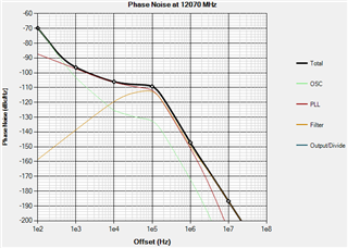 Fig_1
Fig_1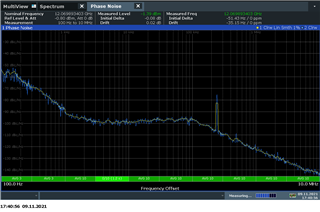 Fig. 1
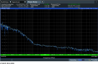 Fig.2
Fig.2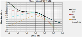
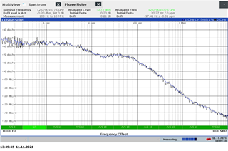 Fig 1
Fig 1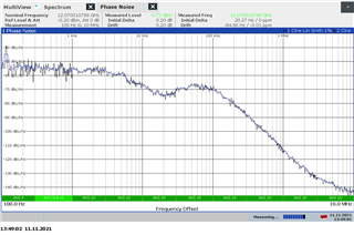 Fig 2
Fig 2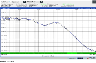 Fig 3
Fig 3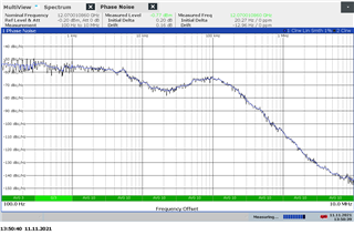 Fig 4
Fig 4 Fig 5
Fig 5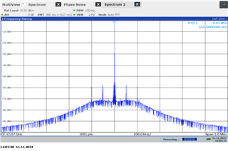 Fig. 1
 Fig. 2