This thread has been locked.

If you have a related question, please click the "Ask a related question" button in the top right corner. The newly created question will be automatically linked to this question.

LMX2595: About VCO calibration

Part Number: LMX2595

I am using it with LMX259512GHz.
We are implementing the recommended power-on sequence.

1. About VCO calibration
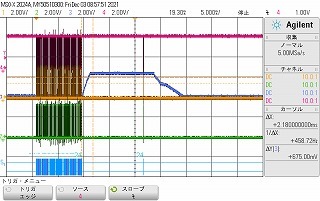
I am monitoring the Vture terminal.
We designed 5 boards and confirmed the following phenomenon on only 1 board.
・ After setting all registers, the voltage will be set to 12GHz (1.3V).
・ After setting all registers, it becomes + 3V as it is, and after 10ms, it becomes 12GHz set voltage (1.3V) at register R0.
・ After setting all the registers, it becomes + 3V as it is, stays at the 12GHz set voltage (1.3V) for about 1ms at the register R0 after 10ms, and then changes to 0V.
Become.

Is it normal operation?

2. About the settings of FCAL_LPFD_ADJ and FCAL_HPFD_ADJ

I made a mistake in setting FCAL_HPFD_ADJ. At Fpd = 200MHz, set R0 (8: 7) 3: fPD> 200 MMHz.
Is the setting of FCAL_LPFD_ADJ and FCAL_HPFD_ADJ important when there is no assist?

I need to explain the details, so I would appreciate it if you could tell me more about VCO calibration.

  • Hi There,

    As you know, the recommended programming sequence is as follows:

    1. Apply power to device.
    2. Program RESET = 1 to reset registers.
    3. Program RESET = 0 to remove reset. (this step is optional)
    4. Program registers as shown in the register map in REVERSE order from highest to lowest. That is, the last register to write is R0 (with FCAL_EN = 1).
    5. Wait 10 ms.
    6. Program register R0 one additional time to ensure that the VCO calibration runs from a stable state.

    ・ After setting all registers, the voltage will be set to 12GHz (1.3V). 

    did you mean after step 4?

    ・ After setting all registers, it becomes + 3V as it is, and after 10ms, it becomes 12GHz set voltage (1.3V) at register R0.

    did you mean after step 6?

    ・ After setting all the registers, it becomes + 3V as it is, stays at the 12GHz set voltage (1.3V) for about 1ms at the register R0 after 10ms, and then changes

    After which step?

  • thank you for your answer.

    ・ After setting all registers, the voltage will be set to 12GHz (1.3V).
    → STEP4.
    ・ After setting all registers, it becomes + 3V as it is, and after 10ms, it becomes 12GHz set voltage (1.3V) at register R0.
    → STEP6.
    ・ After setting all the registers, it becomes + 3V as it is, stays at the 12GHz set voltage (1.3V) for about 1ms at the register R0 after 10ms, and then changes
    → STEP6.

    The attached image is an image when all the registers are set, then it becomes + 3V as it is, and after 10ms, it stays at the 12GHz set voltage (1.3V) for about 1ms at the register R0, and then changes.

  • Hi There,

    ・ After setting all registers, the voltage will be set to 12GHz (1.3V).
    → STEP4. --> That means it is locked to 12GHz after step 4.
    ・ After setting all registers, it becomes + 3V as it is, and after 10ms, it becomes 12GHz set voltage (1.3V) at register R0.
    → STEP6. --> That means it is locked to 12GHz again after step 6.
    ・ After setting all the registers, it becomes + 3V as it is, stays at the 12GHz set voltage (1.3V) for about 1ms at the register R0 after 10ms, and then changes
    → STEP6. --> I don't understand this statement, did you mean after step 6, it only locked for 1ms and then unlock?

  • thank you for your answer.

    I don't understand this statement. Did you mean that after step 6, it was locked for 1 millisecond and then unlocked?
    → Yes. After turning on the power, the lock is released even though it is set to a fixed frequency of 12GHz. We are investigating this phenomenon.

    STEP4 Is it necessary to set FCAL_EN = 1 for the last R0 register even without assistance (set frequency 12GHz)?

  • Hi There,

    We must set FCAL_EN = 1 except for full assist mode, otherwise we won't get the VCO correctly calibrated and locked.