This thread has been locked.

If you have a related question, please click the "Ask a related question" button in the top right corner. The newly created question will be automatically linked to this question.

LMX2492EVM: Inquiries

Part Number: LMX2492EVM
Other Parts Discussed in Thread: LMX2491, LMX2492, CODELOADER, LM6211, LP5900, USB2ANY, LMX2594

Hi Team,

Our customer bought the LMX2492EVM development kit with the LMX2491 component installed. He has some inquiries as follows:

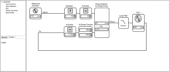
1. Not specified on the data sheet VCO voltages and although the estimate works on 5V the VCO installed has a range of 14V so I wanted to know what the range is?
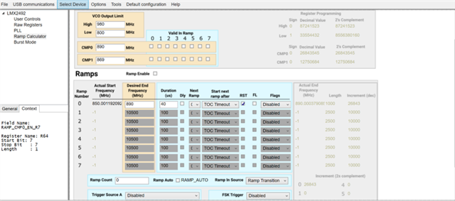
2. I am trying to build my own GUI interface for this component and specified in the user guide of code loader some VBA commands but some of them do not work and lack a lot of parameters like panel names etc ...
3. There are two development kits on your site for the LMX2492 component when in one of them you get an output of the frequency divided by 4 and I wanted to ask why I did not get it? And is it possible to assemble it?
4. Is it possible to access the DLL and EXE files or even the names of the functions built into them so that I can attach them to my project

Regards,

Danilo

  • Danilo,

    1. Charge pump can go to 5V. VCO supply may have a tuning range up to 14V. In that case, an external level shifting amplifier will still be required to reach the full tuning voltage of the VCO.
    2. Consider using TICS Pro instead of codeloader, which is a newer piece of software and which supports LMX2491. As of 1.7.3 revision, TICS Pro has a built-in localhost TCP server which can accept commands to automate GUI interactions. In the TICS Pro program directory (C:\Program Files (x86)\Texas Instruments\TICS Pro) we include a python file called TICSPro_TCP.py which demonstrates how to create a client that can interface with the TCP server.
    3. I'm not sure what you are referring to with the two development kits... Can you provide links to both? We should only have one EVM for this device as far as I know.
    4. We have access to this capability in TICS Pro as described above. I'm not sure exactly what function you're requesting, but LMX2491/LMX2492 use an older-style GUI that has much of the PLL and math functionality built into the executable without the intention of exposing this to the end user programmatically. If there's some function in particular you're looking to use, and you can't access it through the means provided in TICS Pro, you can describe it and we may be able to provide a workaround or a functional equivalence.

    Regards,

    Derek Payne

  • Hi Derek,

    Thank you for your swift response. Please see the feedback of our customer below.

    Thank you for coming back to me 

    So regarding the two development kits attached are two links

    1. www.ti.com/.../snau160e.pdf

    2. static5.arrow.com/.../snau160c.pdf

    As you can see these are two different development kits for the same component

    Regarding the software I want to connect to a development evaluation and after initial loading of the default values ​​I want to give the user an option to enter the start frequency, end frequency and scan time, duration, and perform the RAMP function

    In order to work with the VCO in ranges of up to 14V as you mentioned the external level shifting amplifier is LP5900-3.3V LDO? and it should be located in TP_VccAMP / TP + VccVCO or somewhere else?

    Is there a video or tutorial that shows how to add the external VCO in its place on the board?

    Regards,

    Danilo

  • Ah, I get it now. Note the literature number in the customer's links are the same, just at different revisions. The SNAU160E board is the current revision of the EVM. The SNAU160C board is a prior revision of the EVM. We had to make BOM changes and stop populating the VCO due to obsolete components, and this resulted in a board layout change to accommodate a new component with a different pinout. The original RFVC1843 used in the arrow EVM is discontinued, so I don't think it will be possible to get this component any more. I'm not sure there are any suitable replacements, and I don't think we've looked for any since the latest revision in 2017, so there may be newer alternatives; but the board revision with the RF/4 wiring is no longer available and has been out of stock for a long time. I could look for the layout files if they wanted to build it themselves...

    No video or tutorial for how to populate external VCO, but I can provide basic instructions:

    • For 14V control, they need a suitable amplifier. The LME49710 actually went EOL a few years ago, but LM6211 is still in production with RRO and up to 24V supply. Since op-amp pinout is fairly standard, there may be better options for this component as well.
    • The supply for this amplifier is provided via AmpVcc net, which has a pinout to connect to VccAMP supply net. VccAMP supply net could be generated with LP5900, but 3.3V is not sufficient to drive up to a 14V signal on the amplifier, hence this component is left unpopulated and only provided in case there are configurations which could benefit from it. In practice you would provide the supply externally to the TP_VccAMP pins and connect R54 and C26 to supply power for the amplifier.
    • R52/R53 and C25 provide the bias point for the noninverting terminal of the amplifier from the charge pump supply VccCP. With some creativity, R52 could be moved to support a level-shifting gain configuration (Active Type C loop filter in PLLatinum Sim terminology).
    • R55 would be populated to link the charge pump output to the inverting terminal of the amplifier.
    • There are several filter configurations supported (using filter types as described in PLLatinum Sim):
      • Active Type A: C1_LF and R55 are the first order components, C2a_LF and R2a_LF are the second order components, and R3a_LF/C3_LF/R4_LF/C4_LF are the third and fourth order components. C2_LF, R2_LF, and R3_LF would be left unpopulated.
      • Active Type B: C1a_LF, C2a_LF, and R2a_LF are the first and second order components. R3a_LF/C3_LF/R4_LF/C4_LF are the third and fourth order components. C1_LF, C2_LF, R2_LF, and R3_LF would be left unpopulated.
      • Active Type C is not supported by default, but could conceivably be reworked onto the board with some creativity. Of course, Active Type C is the configuration that allows gain, and that would give the full tuning range for the amplifier... if I were to attempt an Active Type C wiring, I would probably populate R52 connected to AmpVb but not VccCP, and run the VccCP side to the output of the amplifier with an external wire. Then I would use C1_LF, C2_LF, R2_LF, R3_LF, C3_LF, R4_LF, and C4_LF as normal, and leave C1a_LF, C2a_LF, and R2a_LF unpopulated. R3a_LF would be populated with 0Ω.
    • For the different VCOs that are supported:
      • The U2-style pinout could be left as-is, though VccVCO should be supplied from an external supply of higher voltage, and C3/C4 should be checked for their voltage rating. Additionally, R4/R6/R7 and R8/R9/R10 may be too small for the output power they are asked to deliver. Double-check that these components will not be stressed beyond their rated power dissipation.
      • The U2p-style pinout requires R14/C5 to be populated for the supply voltage, and R4_LF/C4_LF should be substituted with R4p_LF and C4p_LF. R5 should be populated, and R6 should be unpopulated. Additionally, R4/R5/R7 may be too small for the output power they are asked to deliver. Double-check that these components will not be stressed beyond their rated power dissipation.

    As long as the customer is comfortable with running TICS Pro in the background to manage the connection between the customer's frontend and the USB2ANY, the TCP server available in versions >1.7.3 provides access to all registers necessary to implement their desired functions.

    Regards,

    Derek Payne

  • Hi Derek,

    Here is the response of our customer.

    Thank you so much for the quick and detailed response!
    Just have not yet received an answer on what can be done about the TICS PRO software, I want to connect to a development evaluation using a simple gui I create and after initial loading of the default values I want to give the user the option to enter the start frequency, end frequency and scan time, duration, and perform The RAMP function. I saw that we get the option to connect to the component with Python code but I would be happy to get the code files of the RAMP function and load the registers or the option to connect with the EXE \ DLL files

    Regards,

    Danilo

  • Danilo,

    We don't have any API exposed to allow connecting to the exe directly (except ActiveX, which will be deprecated within 1yr, and requires the other program to run as a 32-bit process).

    The logic for the LMX2492 ramp function is actually stored in plaintext as a .py file for evaluation. TICS Pro uses IronPython to directly load python functions into the application scope, to handle some of the logic:

    • The ramp calculations should be located in C:\ProgramData\Texas Instruments\TICS Pro\Configurations\Devices\PLL\LMX2492\LMX2492_rampcalc.py
    • By TICS Pro convention, functions ending with "_Update" are linked to controls in the GUI. Any time the control is modified by user interaction (mouse control, TCP server control) the update function is called. 
    • Controls are given an iValue, dValue, or sValue corresponding to integer, float, or string data types. Register-backed controls with an iValue correspond to the register programming value.
    • Whenever we write to a register-backed control with a .iValue update, this is translated to an immediate register write.

    I think this should be sufficient to do what they're asking.

    Regards,

    Derek Payne

  • Hi Derek,

    We just received this update from our customer.

    I was able to connect to the tics pro software and now I am trying to work on the Python file of the RAMP CALC but as soon as I run it it shows me errors so I wanted to know how it can be used so that it works together with the TCP file that the 2492EVM board has

    Regards,

    Danilo

  • Danilo,

    Without the errors, I can't do much debugging. Can they provide this?

    To clarify: the TCP file is used to control a running instance of TICS Pro, and is not related to the rampcalc file. The TCP file would be useful if you wanted to design your own GUI so that it sends API commands to a running instance of TICS Pro. If your GUI needs to run without interacting with TICS Pro in any way, the TCP file will not be useful to you.

    The rampcalc file is part of the LMX2492 device profile and is not intended to be run standalone. The suggestion I made in the previous post was that you could conceivably convert rampcalc to a standalone module which you could integrate into your application by building the equivalent TICS Pro pieces yourself (parsing the device ini and generating compatible objects that map to the necessary device fields). Otherwise, you can read the function in rampcalc and determine how to replicate the script behavior in your own software.

    I will suggest some of the issues I see as likely to come up:

    • TICS Pro uses IronPython2.7, so the python within rampcalc is compatible with python2.7. There may be some 2-style conventions that are no longer resolved correctly in python 3.x
    • TICS Pro python files will have some imports for .NET Framework elements. For example, imports from System.Windows and sub-assemblies are not supported by standard python.
    • We sometimes use direct assignment to objects beginning with "UIC_" - these are user input controls and are .NET Framework elements. They should be commented out.
    • There are some functions such as Dim and UnDim which are used to control visual styling, and they can be overridden with pass functions or commented out.

    Regards,

    Derek Payne

  • Hi Derek,

    According to our customer,

    Hi, I soldered VCO in its position on the LMX2492EVM board as recommended on the manufacturer's pages so it's a CVCO55CL-0800-0980 L5. When I connected the device I got a constant voltage in a tune of 5 volts that does not change even though I tried to change frequencies in the software it did not help.

    I would be happy if you could tell me what I need to change in addition and what values so that I can sweep in the desired frequency range (800-980 MHz) for example maybe need to change the value of capacitor C2 to replace resistor values and the like?

    Strange that there is no guide like the oscillator replacement guide ...

    Regards,

    Danilo

  • Hi Danilo,

    Could you tell us exactly what did the customer change? For example, I know a new VCO is populated, what other components were change as well?

  • Hi Noel,

    Here are the changes made by our customer.

    1) I removed the resistor R6 and connected it to the resistor R5

    2) I removed the resistor R4_LF and connected it to R4PLF

    3) I disconnected the L4, L5

    4) I connected the R14 and C5

    I checked with FLUK that everything is connected properly and updated the VCO in the TICS PRO software for example to a frequency of 850MHZ and what I get is that the circuit fails to lock and the frequency you get is 980MHZ with a TUNE voltage of 5V and any change in the software does not affect the frequency change, Do I need to make any further changes to the board so what are they?

    Another question that came to my mind is the connection of the USB2ANY component does not set a new COM and I see that there is a DLL library on the component, I wanted to ask how you can communicate with the component without the TICSPRO with communication to USB2ANY and from there talk to the component. I mean I would love to have access to functions that do not work in the USB2ANY component in the SPI communication in order to send the commands manually and not through the TICS PRO

    Regards,

    Danilo

  • Danilo,

    US holiday for TI today, so I'll look into this in more detail tomorrow. My "ten seconds of thought" guess is the feedback loop is broken, or the polarity on the charge pump is incorrect. At a bare minimum, I would expect changing the charge pump polarity should force the TUNE voltage to 0V rather than 5V.

    As far as setting up USB2ANY manually, we have some documentation in other E2E posts describing how this is done (see the link below, which includes the API manual for USB2ANY v2.7.0.0 bundled with TICS Pro). That said, I've since observed a few errors in how I wrote that program, and it's specific to LMX2594, so I've included an updated snippet after the link.

    https://e2e.ti.com/support/clock-timing-group/clock-and-timing/f/clock-timing-forum/1025934/lmx2594evm-serial-control-through-python

    import ctypes
    u2adll = ctypes.WinDLL(r"C:\path\to\USB2ANY.dll")
    
    ## [Scan available USB2ANY devices]
    controllers = []
    buf = ctypes.c_buffer(80)
    for i in range(u2adll.u2aFindControllers()):
        u2adll.u2aGetSerialNumber(i, buf)
        if buf[0] != b'\x00':
            # USB2ANY serial number response is encoded in 16 bytes
            controllers.append(buf[:16])
    
    # Open a session with USB2ANY. In our example, use the first one.
    if not controllers: raise Exception('no USB2ANY found')
    handle = u2adll.u2aOpen(controllers[0])
    
    ## [Configure SPI bus]
    bitRateKbps = 400
    divider = int(24000 / bitRateKbps)
    dividerHigh = (divider >> 8) & 0xFF
    dividerLow = (divider & 0xFF)
    errCode = u2adll.u2aSPI_Control(
        handle, 
        1,      #SPI capture on leading edge
        0,      #SPI inactive state low
        1,      #SPI MSB first
        0,      #SPI 8-bit
        1,      #SPI with every packet
        1,      #SPI active low
        dividerHigh, dividerLow)
    if errCode != 0: raise Exception('failed to configure SPI bus: ' + str(errCode))
    
    ## [Write and Read example]
    denominator = 0xFACADE
    buf = ctypes.c_buffer(3) #register length is three bytes for LMX2594
    packet1 = 0x001500 + ((denominator >> 16) & 0xFF)
    packet2 = 0x001400 + ((denominator >> 8) & 0xFF)
    packet3 = 0x001300 + (denominator & 0xFF)
    
    # first packet
    buf[0] = (packet1 >> 16) & 0xFF
    buf[1] = (packet1 >> 8) & 0xFF
    buf[2] = packet1 & 0xFF
    bytesWritten = u2adll.u2aSPI_WriteAndRead(handle, 3, buf)
    # assert bytesWritten == 3
    
    # second packet
    buf[0] = (packet2 >> 16) & 0xFF
    buf[1] = (packet2 >> 8) & 0xFF
    buf[2] = packet2 & 0xFF
    bytesWritten = u2adll.u2aSPI_WriteAndRead(handle, 3, buf)
    
    # third packet
    buf[0] = (packet3 >> 16) & 0xFF
    buf[1] = (packet3 >> 8) & 0xFF
    buf[2] = packet3 & 0xFF
    bytesWritten = u2adll.u2aSPI_WriteAndRead(handle, 3, buf)
    
    # readback example - we will read 0x13
    buf[0] = 0x00 | 0x80 # high bit is 1 for readback
    buf[1] = 0x13
    buf[2] = 0x00
    bytesWritten = u2adll.u2aSPI_WriteAndRead(handle, 3, buf)
    assert (packet3 ^ ord(buf[2])) & 0xFF == 0 # 0x13 reads back as 0xDE
    
    ## [when done, close session]
    u2adll.u2aClose(handle)

    Regards,

    Derek Payne

  • Hi Danilo,

    The hardware modification is correct.

    With the new 800M - 980MHz VCO, the fpd needs to be reduce to 50MHz or lower in order to meet the min. N-divider requirement.

    For example,

  • Hi Noel,

    Here is the feedback of our customer.

    I tried what Noel Fung suggested and now some things work and some do not

    My desire is to perform a sweep from a frequency of 869-890MHz but I can not set the start frequency in VCO and also that I try a frequency of 870MHz The start frequency is stuck at 850MHz in addition the device does not turn on the LED when performing the sweep

    I would love a guide who will tell me what I need to do in terms of what other parameters I need to change and why?

    I have to perform the sweep at high speed so is there a formula where I can know what the maximum speed is and what the minimum speed can be performed on the device with the VCO I assembled?

    Regards,

    Danilo

  • Hi Danilo,

    here is an example .tcs configuration, you should get a sawtooth ramp after clicking the Ramp Enable checkbox. 

    e2e2492.tcs

    Please study the operation from datasheet and EVM user's guide. Please also read the LMX2491 datasheet and user's guide, we have added more examples in there. 

  • Hi Noel,

    I have deleted my last post as request by our customer due to confidentiality reason. HIs inquiries have been resolved. Thank you very much for your help!

    Regards,

    Danilo