This thread has been locked.

If you have a related question, please click the "Ask a related question" button in the top right corner. The newly created question will be automatically linked to this question.

TICSPRO-SW: Error writing into register

Part Number: TICSPRO-SW
Other Parts Discussed in Thread: LMK05318BEVM, LMK05318B, USB2ANY, MSP430F5529

Hi Team,

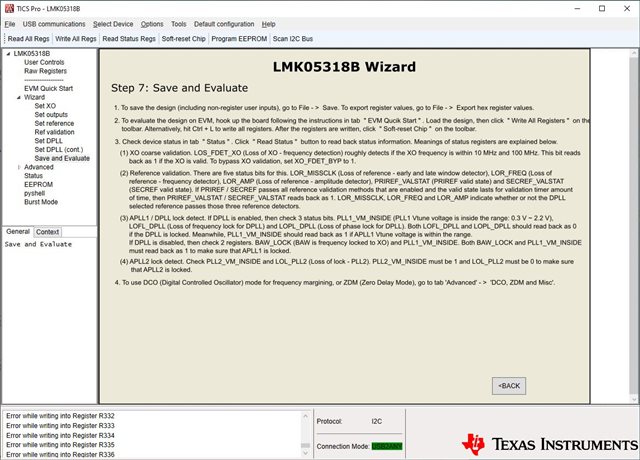
Our customer is using the LMK05318BEVM evaluation module and encountered an error message "Error writing into register" as shown in the screenshot below.

According to our customer,

When I try to scan for I2C address I get no devices found.

When I look at the directions on Step:7 of the tool, Item 2 says use "EVM Quick Start" tab. There is no such tab in the tool. 

I'm using the demo board in the 'out of the box' configuration. Is there a setup issue?

Regards,

Danilo

  • Danilo,

    This is probably not the issue, but is there power being supplied to the LMK05318B? The EVM requires both a USB connection and an external supply. If scanning the bus is working but reveals no devices, this could indicate the device is unpowered.

    Are the I2C header jumpers populated, so signal is reaching the device? Can you probe the I2C signals and inspect if the signal is actually working?

    TICS Pro accumulates error logs for failed writes like this, can you check the TICS Pro install location (C:\Program Files (x86)\Texas Instruments\TICS Pro) and check the error log? Depending on what kind of I2C error we're getting, this could help us debug.

    Regards,

    Derek Payne

  • Hi Derek,

    Thank you for your response. According to our customer,

    Subsequent to my initial request I found that one of the power jumpers was in the incorrect position. I can now communicate with the LMK5318B part on the eval board but cannot seem to get an output from the clocks when I download a program file.

    The reason I’m using the eval board is because I’m trying to debug a design using the same chip. In my design the chip on the board returns an ID of 7CH when I Scan I2C Bus using the TCIS Pro tool and a TI USB2ANY pod. I can use the pod to talk to the LMK05318B part on the eval board via the eval board’s J4 interface. I’ve configure the eval board identically to my design and the Scan I2C Bus operation on the eval board returns 64H for the device where my design returns 7CH.

    So, I have two problems. Generating a clock output and getting essentially the same design on my board to communicate to the pod.

    For the clocking problem, I’m attaching my program file. My input to the PRIREF_P SMA, J17 on the eval board, is a 25MHz clock output from a LVDS driver.

    Regards,

    Danilo

  • Hi Derek,

    We just received additional inquiry from our customer.

    My design uses a 1.8V PU for the I2C interface. This goes to an FPGA using 1.8V power. I’ve determined that the TI USB2ANY I2C interface only operates at 3.3V. I tried removing the internal PU resistors in the USB2ANY and using the Pus on my design but the I2C interface does not function. Reinstalling the resistors makes the interface function but the SCAN I2C Address returns 7CH instead of the 64H that the LMK5318B is wired for.

    Question: Is my assertion that the USB2ANY pod is 3.3V only? If so, is there another TI pod that we can use?

    For now I’m going to shift to the problem of getting the demo LMK05318B demo board to load and run.

    Regards,

    Danilo

  • Danilo,

    Yeah, unfortunately USB2ANY is based on I/O levels for MSP430F5529 which does not support 1.8V I/O. You would need a level shifter between the USB2ANY and the 1.8V domain. We don't have another solution at this time. You can export the hex register values from TICS Pro once you get the demo board working how you like, and load those in through a different bus controller.

    The five MSBs of the I2C address can be modified by overwriting EEPROM values. I suspect they have overwritten the EEPROM or loaded a value from EEPROM that modified these address bits.

    Regards,

    Derek Payne

  • Hi Derek,

    According to our customer,

    I’ve tested the theory that the EEPROM bits were overwritten but am having issue getting them back to the default value to provide 064H as the device address. Looking at the Extra EEPROM Bytes on the EPROM page I find that the value displayed in the GUI is 248. This seems to be a Decimal value instead of a Hex value. It converts to F8H. Assuming that this represents the address as described I the LMK05318B data sheet, Table 9 the address responded to by the device should be 078H (assuming the max address field is 7 bits and that the MSB is truncated), not 07CH.  It looks like the bits are shifted from the definition in Table 9.

    I converted 064H into a decimal value of 100 and programmed the EEPROM with that value. The address changed to 030H, not 064H.

    Questions:

    1. Why does the GUI display a Decimal value for a Hex field?

    2. Is the description for Address Byte 10 in Table 9 correct? If so, then why the operation I’m seeing?

    I’ll try to identify how to correctly program the default address value back into the part but I’d like clarification on the interface definition.

    Regards,

    Danilo

  • Hi Derek,

    I just received this update from our customer,

    My present status with this integration is that I was finally able to get the demo board configured for the outputs of our design but have not been able to move the design onto the board we designed. I am unable to get the DLL to phase lock. I believe this is due to the clock input which we originally had as a 1.8V logic single ended drive. We’ve changed that drive buffer to a 2.5V powered logic after we determined that the spec stated the input needed to be above 1.8V but are still unsuccessful. Do you have a recommended driver for the PRI_REF input in single ended mode?

    Regards,

    Danilo

  • Danilo,

    Now that the clock is 2.5V there should be no issues with a SE-style input interface. As long as slew rate is at least 0.2V/ns (preferably >0.5V/ns) the input amplitude and slew rate should not prevent phase lock.

    The customer cannot get phase lock. Can they get frequency lock, or frequency validation on the input reference? If they can get frequency validation, the problem is not the input reference, and is more likely an interaction between the XO stability and the input stability. Can I get the input frequencies (XO, input reference), the XO stability, and the DPLL loop bandwidth/TDC frequency?

    Alternately, if I can get either the tcs file (preferred) or the hex register programming and the input/XO frequencies, I can directly inspect these parameters for any potential issues.

    Regards,

    Derek Payne

  • Hi Derek,

    According to our customer, the issue has been resolved.

    I’ve resolved the problem. The 33ohm series source resistance on the schematic was interacting with something internal to the TI chip. This was true in any of the terminating modes of the chip. The signal output of the driver was clean but the signal at the chip was distorted. Eliminating the series resistance resolved the waveform problem and let the chips to lock. Thanks for this.

    Thanks for your support!

    Regards,

    Danilo