This thread has been locked.

If you have a related question, please click the "Ask a related question" button in the top right corner. The newly created question will be automatically linked to this question.

TLC555: Maximum timing capacitor and maximum discharge current

Part Number: TLC555

Thank you for your explanation.

My question is the maximum capacitor capacity and maximum discharge current.
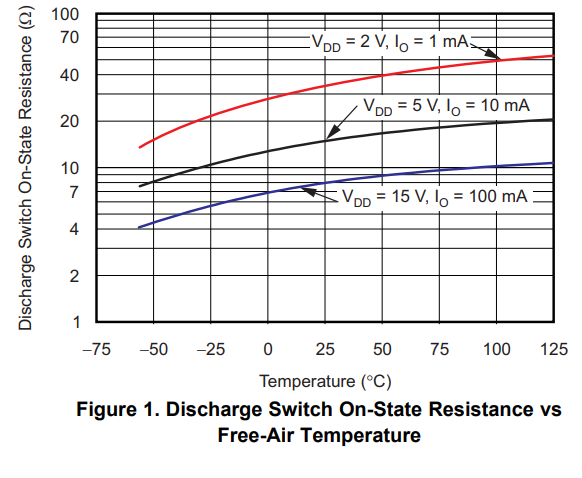
Since it is not specified in the data sheet, I think it will be determined by power consumption and heat calculation.
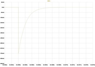
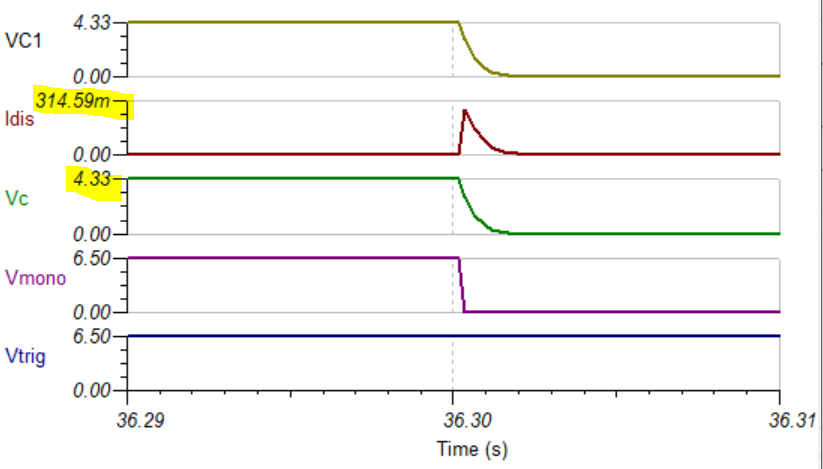
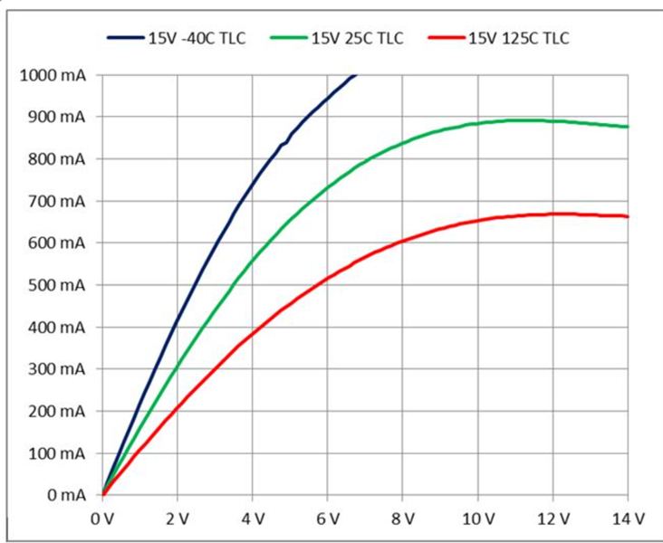
When simulating with LTspice, the peak discharge current from 32uF flows 720mA.
The power consumption is calculated from the current and voltage, and the average power consumption is calculated from the discharge time interval.
Multiply it by thermal resistance to calculate the temperature rise.
I understand that if the temperature is below the junction temperature, it will not break.
Is it correct?

I wonder if 720mA will actually flow in the device.
Is there an internal resistance in the discharge FET inside the IC, and is it limited by the maximum discharge current that can be passed?

  • Hello,

    We do not have a specification or method for calculating the max capacitor value, however we do have some results below from prior experiences and a good simulation model to help. 

    The capacitor will charge up to 2/3*6.5V = 4.33V. I labeled this as Vc in the plot below. The online calculator (attached below) gives us an estimate of the discharge on resistance (ron) of roughly 13.9 ohms. This aligns with estimating from the pds curve for ron as well. 

    The Tina spice model is a transistor based replica of the design and will provide the most accurate result. I see a discharge current of 314.6mA. This aligns closely with 4.33V/13.9ohm = 312mA from our estimated resistance value. 


    I found a post that has a scenario that is much higher than yours. Our engineer tested with 150uF at a supply of 15V. The part functioned as expected in that scenario and the timing was consistent between tests.

    Here is the post for this scenario. 

    https://e2e.ti.com/support/clock-timing-group/clock-and-timing/f/clock-timing-forum/946694/tlc555-how-to-calculate-current-flow-through-transistor-when-timing-capacitor-is-discharging

    In addition we have sample data that was provided on that post as well. Although this is at high supply it is a scenario which draws more current than your application which gives confidence. 

    Regarding the current value into the discharge pin AMR is abs max rating table:

    "The AMR table wants the designer not to exceed the rating. If the device, on it own choice, seems to violate the spec then that is usually acceptable. The data sheet shows the normal example has a capacitor directly on the discharge pin. So the data sheet recommends having this capacitor directly attached and makes no mention about calculating peak current or adding resistance. In this case the AMR limit would not apply to the capacitor." 

    Please refer to this post: https://e2e.ti.com/support/clock-timing-group/clock-and-timing/f/clock-timing-forum/915841/tlc555-q1-absolute-maximum-rating-of-disch-pin

    Yes this is correct, if the temperature stays below the abs max the device will be ok. 

    The recommended operating temperatures should be observed. 

    3580.Monostable 30 Seconds.TSCslvc100a (12).zip

    Best Regards,

    Chris Featherstone