This thread has been locked.

If you have a related question, please click the "Ask a related question" button in the top right corner. The newly created question will be automatically linked to this question.

CDCI6214: CDCI6214 clock chip initialization

Part Number: CDCI6214


Dear Team,

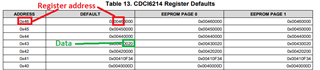
The clock chip CDCI6214 Ultra-Low Power Clock Generator With PCIe Support, Four Programmable Outputs and EEPROM used in the project.
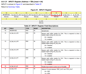
Which register should be written for the initialization of this clock chip? Write what? What does the control timing and logic look like? Can you provide reference logic code or documentation?

Many Thanks,

Jimmy

  • Hi Jimmy,

    For programming the device, the detailed register programming sequence is described in the datasheet section 8.5 Programming. 

    with TICS Pro (https://www.ti.com/tool/TICSPRO-SW) you can generate device settings. If you have an EVM you can even program the device through this software.

    Let me know if you have further questions.

    Thanks!

    Regards,

    Ajeet Pal

  • Hi Ajeet,

    We appreciated your great support!

    Can you elaborate on the difference between "register commit" and "EEPROM direct access". ——datasheet section 8.5.2

    In addition, I don't understand "device defaults".——datasheet section 8.5.3  Can you explain the meaning of "table 13" and "table 14".  Should I configure "device default" or "EEPROM Page0 / 1"

    Many Thanks,

    Jimmy

  • Hi Jimmy,

    Register commit and EEPROM direct access are the two ways of programming the EEPROM.

    Register commit is the process, where EEPROM data is copied from the device register after configuring the device (like configure it in TICS pro and load on device then copied to EEPROM).

    Whereas in EEPROM direct access, EEPROM data directly write through I2C interface. For both the programming sequence mentioned in datasheet.

    Regarding the table 13 and table 14 data, the factory device comes with default data settings and whereas EEPROM page 0 and EEPROM page 1 data are defined for the pre-config settings for figure 29 and figure 30 setup.

    Thanks!

    Regards,

    Ajeet Pal

  • Hi Ajeet,

    We appreciated your great support always!

    1. Why is the register address in Table13(Table14) a byte? And the value(in Table13) is 4 bytes? In table 14, the value is two bytes? Inconsistent with figure 27. I don't quite understand.
    2. If we configure device through EEPROM direct access, can we just look at table 14 and ignore table 13?
    3. In figure 29 and figure 30,the Y0 is disabled. Does this indicate that the chip has no output by default Y0?

    Many Thanks,

    Jimmy

  • Hi Jimmy,

    1. Why is the register address in Table13(Table14) a byte? And the value(in Table13) is 4 bytes? In table 14, the value is two bytes? Inconsistent with figure 27. I don't quite understand.

    Table 13 shows the register address also with 2 byte, where MSB byte kept 00, next byte shows the register address and other 2 byte is data, which is similar protocol mentioned in Figure 27.

    Table 14 is a EEPROM image data with register address and data, it is similar as Figure 28 for EEPROM direct access using I2C. Register address is 6bits and data is 8 bits.

    If we configure device through EEPROM direct access, can we just look at table 14 and ignore table 13?

    Yes, that's correct. For EEPROM direct access, need to follow the figure 28 data sequence similar as Table 14.

    In figure 29 and figure 30,the Y0 is disabled. Does this indicate that the chip has no output by default Y0?

    Default Y0 output is disabled. it can be enable with 0X1B[10] --> 1.

    Thanks!

    Regards,

    Ajeet Pal