Other Parts Discussed in Thread: LMK04906
Hi Team,
LMK5C33216 datasheet mentioned that can realize hitless switching between two ref input. So I have several questions about it.
1. Does the hitless switching function is unique for DPLL only? I found in APLL jitter cleaner, such as LMK04906, it also have the hitless switching and phase cancellation. So I want to know if they are same or not?
2. What is the background principal of phase cancellation and slew rate control?
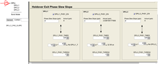
3. How to set the DPLLx_PHS1_THRESH and DPLLx_PHS1_TIMER register value? Can I calculate it as Maximum phase error=1/Fpfd=DPLLx_PHS1_THRESH*DPLLx_PHS1_TIMER?
Thanks and looking forward to your reply!
B.R.
Zhizhao
B.R.
Zhizhao