This thread has been locked.

If you have a related question, please click the "Ask a related question" button in the top right corner. The newly created question will be automatically linked to this question.

LMX2595: in manual Ramp mode

Part Number: LMX2595

Hi team,

Another customers' question.

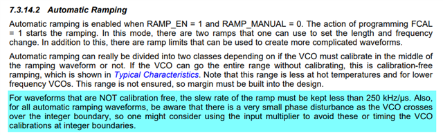
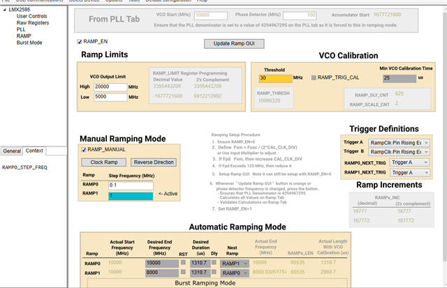
For manual ramp, is the clutter at an integer multiple FPD frequency a phase interference, (integer boundary clutter)? Does this have an effect on the continuity phase? Here the clutter is one occurring at an integer multiple FPD and one symmetrically on the other side of the main signal, as shown in the figure:

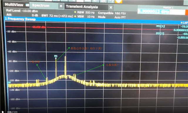
Is there a way to avoid or eliminate this clutter of integer boundaries? Does TI have quantitative data on the effect of the initial mash order on this integer boundary in ramp mode? 

Best Regards,

 Amy Luo

  • Amy,

    Can we get the programming that's being used to generate this screenshot?

    I suspect the spurs seen at multiples of FPD are phase detector spurs; there should be some effect on their amplitude when reducing charge pump current or loop bandwidth. But another cause may exist depending on the specific programming.

    There should only be an effect on the phase during ramping if the N-divider increments or decrements (in other words, if an integer boundary is crossed in the feedback path). As long as the integer portion of the N-divider remains constant, no phase hit should be observed.

    Again, it would help a lot if we can get the programming used to generate this screenshot.

    Regards,

    Derek Payne

  • Hello Derek,

    The Customer's feedback

    Having tried charge pump has little effect on this; whether the input clock is differential or single-ended does not matter; whether analogue and digital power is separated does not matter.

    There should only be an effect on the phase during ramping if the N-divider increments or decrements (in other words, if an integer boundary is crossed in the feedback path). As long as the integer portion of the N-divider remains constant, no phase hit should be observed

    As shown in the video above, there is a fixed position exactly at the FPD multiples, where the N changes. Can the varying phase interference here be reduced? In what way they can be reduced or avoid this

    Best Regards,

     Amy

  • Hi Amy,

    Couples of reason:

    1. Fractional spurs

    Since fpd = 100MHz but the ramp step is 1MHz. At 10000MHz output, there is no spurs. But when you ramp the frequency between 10001MHz and 10099MHz, you will see fractional spurs. These spurs are unavoidable because the PLL is in fractional mode. 

    2. Ramp clock spurs

    if we continue to sweep the frequency, this is equivalent to frequency modulate the PLL, in other words, we are doing FM modulation. As a result, there will spurs (modulation) equal to the modulation frequency (= ramp clock frequency). Higher ramp clock frequency will push the spurs frequency to a higher offset frequency and as a result, lower spurs. 

    3. VCO calibration

    You have the ramp threshold set to 30MHz, since ramp step is 1MHz, so there will be a VCO calibration every 30MHz ramp is elapsed. During VCO calibration, there will be unwanted spurs or glitches. If the ramp range is less than 100MHz, maybe we can sweep the frequency without a VCO calibration, but this calibration-free  range is not guarantee.