Other Parts Discussed in Thread: LMK05028
Hi Team,
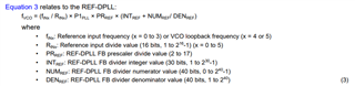
Question: Please let me know how to configure DPLx feedback divider registers properly through TICS Pro GUI.
Following your advice, I tried the following procedure.
- Supply 5 V power to the EVM
- Apply 25 MHz, 0-2 V reference clock.
- Run TICS pro Version 1.7.5.0
- Click Select device => Network-- => LMK05028
- Click Default Configuration => EVM Default
- Moved to the main script page
- Click Update frequency plan
- Click RUN Script
- Click Write All registers
- Click Soft Reset Chip
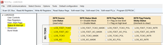
- Checked LEDs for Stats 1 and 2.
They were still light on.
LEDs for the hold over were on or off corresponding to the
presence and absence of the REF clock.
I concluded that DPLL1 nor DPLL2 did not get lock.
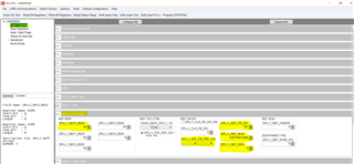
I checked register related to the PLLx feedback path
and found that they might be inappropriate values as follows:
Please let me know how to set valid values for these registers.
DPLL1: VCO freq.= 5000 MHz
Post Div = 4
Out Div for port 7 = 8
Out7 Freq. = 5000/4/8=156.25 as expected
On the feedback path
Pre-Div R362 = 0x02 resulting 4
Feedback Div. R363~R366=0x313 = 787
Num R367~R371 = 0x80 00 00 00 00
DEN R372~R376 = 0x00 00 00 00 00
Ignoring Num and DEN, the feedback frequency was 5000/4/4/787=0.397078 MHz.
~~~~~~~~~~~~~~~~~~~~~~~~~~~~~~~~~~~~~
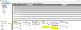
DPLL2: VCO freq.= 5529.6 MHz
Post Div = 5
Out Div for port 0 = 9
Out0 Freq. = 5529.6/5/9=122.88 as expected
On the feedback path
Pre-Div R501 = 0x01 resulting 3
Feedback Div. R502~R505=0x0e = 14
Num R506~R510 = 0xbe df a4 3f 18
DEN R511~R515 = 0xff ff ff fe ec
Ignoring Num and DEN, the feedback frequency was 5529.6/5/3/14=26.3314 MHz.
Please let me know how to configure these registers properly through TICS Pro GUI.
Mita