This thread has been locked.

If you have a related question, please click the "Ask a related question" button in the top right corner. The newly created question will be automatically linked to this question.

LMK05318B: New device recommendation

Part Number: LMK05318B
Other Parts Discussed in Thread: LMK5C33216, LMK5B33216, LMK05028, LMK5B12204, LMK04033, LMK04000, LMK04001, LMK04011, LMK04010, LMK04002, LMK04031, LMK04610, CDCE813-Q1

 Hi team:

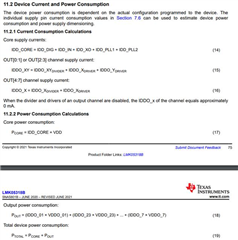
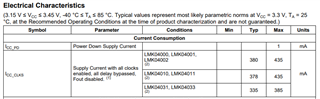
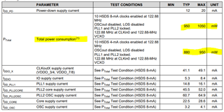
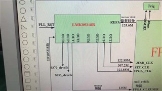
 I would like to confirm whether we have a low consumption device as <1W  to substitute the LMK05318B.

 tks for you confirmation.

  • Hello Allen,

    Can you please provide more information on your required frequency plan?

    1. What will be your XO input frequency?

    2. How many outputs are required and what are there frequencies?

    3. What will be the required output formats (LVDS, LVPECL, HCSL, etc.)?

    4. Will you require the DPLL? If yes, what is your reference frequency?

    Depending on your configuration, the LMK05318B could possibly have below 1 W consumption.

    Can you also please provide the required output jitter performance required for your output clocks?

    Most of our network synchronizer devices require a 3.3 V supply so the consumption will probably be > 1 W, but if performance is not of high importance, there are a few options that support a lower supply voltage and therefore a lower consumption.

    Also please note that the following link shows all of our clock jitter cleaners and synchronizers for your reference: Clock jitter cleaners and synchronizers

    Regards,

    Kia Rahbar

  • hi Rahbar:

     tks for your detail explanation. i would double confirm the spec with the customer and feedback to you. 

     Besides, i try to use the LMK05318B device in lower consumption by disable APLL1 and active APLL2 only, but i found that all the output are disappear. in this case, would you share the guide to me ,how to set this config-files?

     tks for your support,

  • besides, would you also share which options that support a lower supply voltage?

  • Hello Allen,

    Here is a presentation that shows you how to use the LMK05318B GUI:

    LMK05318B TICS Pro GUI Overview.pdf

    The following link shows all of our clock jitter cleaners & synchronizers: TI clock jitter cleaners & synchronizers

    All of the devices will likely have > 1W power consumption.

    To get below 1 W, you will need to use less outputs, a single PLL, and low current drawing output format (such as LVDS).

    For example, Section 11.2 in the data sheet provides the equations for calculating the approximate power consumption for the LMK05318B.

    Using the equations above and configuring the device to use APLL1 only, OUT0/OUT1 only, and LVDS output format, the power will be as follows.

    We have:

    • IDD_CORE = IDD_DIG + IDD_IN + IDD_XO + IDD_PLL1 + IDD_PLL2
      • IDD_DIG = 21 mA (Typ)
      • IDD_IN = 43 mA (Typ)
      • IDD_PLL1 = 110 mA (Typ)
      • IDD_XO = 20 mA (Typ)
      • IDD_PLL2 = 20 mA (Typ; isn’t used, so should be disabled)
      • *From 7.6 Electrical Characteristics table:
      • IDD_CORE = 214 mA
    • Pcore = IDD_CORE * VDD = 214 mA * 3.3 V = 706.2 mW


    • IDDO_0/1 = IDDO_01DIVIDER + IDDO_0DRIVER + IDDO_1DRIVER
      • IDDO_0/1 = 70 mA (typ; divider value >6)  + 11 mA (LVDS; Typ) + 11 mA (LVDS; Typ)
      • IDDO_0/1 = 92 mA
    • Pout = (IDDO_01 × VDDO_01)
    • Pout = (92 mA) * 3.3 V
    • Pout = 303.6 mW

    • PTOTAL = Pcore + Pout
      • PTOTAL = 1.0098 W

    As you can see, even with using 2 outputs and a single PLL, this device will still be above 1 W power consumption.

    The same situation will occur with all of our other network synchronizers (LMK5B12204, LMK05028, LMK5B33216, LMK5C33216).

    Therefore, if you need a device with DPLLs (network synchronizer), you will most likely have above 1 W power consumption.

    Our jitter cleaners (LMK04000, LMK04001, LMK04002, LMK04010, LMK04011, LMK04031, LMK04033) will also have a power consumption above 1W.

    These jitter cleaners have a current consumption as shown below:

    If we take the smallest value of 335 mA, we still get a power consumption equal to 1.1055 W (335 mA * 3.3 V).

    The reason our jitter cleaner & network synchronizer devices will rarely have below 1 W power consumption is because they have a 3.3 V supply.

    The LMK04610 would be your best and only option (other than the CDCE813-Q1 which has 3 outputs).

    The LMK04610 would have a consumption as shown below:

    Regards,

    Kia Rahbar

  • Hi Kia:

     Tks for this details sharing. i will check with the customer and promote the new device to them.

     beside ,i want the confirm with you that how to disable the APLL1 and use APPL2 only?  I check the block diagram inside, seems like the DPLL connects to the APLL1 but not APLL2 also.  so my customer is seeking a solution to reduce the consumption by disable the APLL1 ,because they need the fractional division function.

  • Hello Allen,

    To disable APLL1 and use APLL2 only, you must perform the following:

    1. Disable APLL1 on the APLL1 page as shown below.

    2. Enable APLL2 and set PLL2 Reference Select to "XO". If PLL2 Reference Select  is set to "VCO1- cascaded Mode (default)", you will not get output clocks from APLL2 because its reference is APLL1 and APLL1 has been disabled.

    I strongly recommend against doing this for the following reasons:

    1. If you use APLL2 only, you will not be able to use the DPLL.

    2. If you use APLL2 only, your output clocks phase noise performance will be worse than using APLL1.

    3. The current consumption is actually greater when using APLL2 instead of APLL1 and the DPLL. As you can see in the image below APLL2 uses 120 mA of current when enabled. APLL1 and the DPLL use 110 mA of current when enabled. When disabled APLL2 use 20 mA of current. When disabled APLL1 and the DPLL will still consume 20 mA (this is not specified in the data sheet, but I have verified in our lab).

    The only case where I would recommend using APLL2 only is if all of your output frequencies are not an integer division of the 2.5 GHz BAW VCO of APLL1. In this case it is not mathematically possible to use APLL1, so you would have to default to APLL2 only.

    If your frequencies are an integer division of the 2.5 GHz BAW VCO, then I strongly recommend using APLL1 only.

    Regards,

    Kia Rahbar

  • Hi Kia:

     many tks with your detail explanation.  I would like to double confirm with you about the BAW frequency lock detect setting as the attached file.

     The customer feedback that if they disable this setting, the end equipment of Opto Module will become more unstable.

     but if enable this setting, the Opto module will become more stable.

     but base on this description in the SW, it is conflict between the DPLL(customer need to enable) and BAW frequency lock detect performance.

     would you help to check this timing config-file and B/D in this case? tks!

     LMK05318B_20220614.TCS

  • Hello Allen,

    The BAW frequency lock detect indicates when the BAW (VCO1) has locked.

    You can have the BAW frequency lock detect and the DPLL enabled at the same time. The description in SW is a recommendation that the BAW frequency lock detect can be disabled when then DPLL is enabled. It is not required to disable the BAW frequency lock detect.

    Regards,

    Kia Rahbar

  • Also after disabling the BAW Frequency Lock Detect, did you ensure the DPLL was properly locked (HLDOVR, LOFL_DPLL, and LOPL_DPLL flags are all low)?

    If the DPLL is not locked, the opto module will be unstable.

    Regards,

    Kia Rahbar