This thread has been locked.

If you have a related question, please click the "Ask a related question" button in the top right corner. The newly created question will be automatically linked to this question.

LMX2572EVM: setting step size while working with trigger in automation mode ramping

Part Number: LMX2572EVM
Other Parts Discussed in Thread: LMX2491, LMX2572, LMX2492EVM

I have the part LMX2572EVM and want to make a sawtooth linear ramp signal from (3600 - 3650 ) MHz within 1 ms.

1st option: Using automatic ramping mode and setting " trigger next ramp" =TOC timeout. the Fpd=100Mhz, so it will ramp every 10 ns; thus, the incremental steps are 50000. each step will be 1KHz. the problem is that there is no flag for the start of each ramp, so it can be used as an indicator for my ADC board to determine the beginning of each ramp.  Is there any solution to this problem?

- 2nd option: using manual ramping and using an external pulse clock to trigger for step increase at the rampclk pin with appropriate frequency. and another clock at the rampdir pin to control the ramping segments as indicated in the user manual. one of the external clock signals can be used as an indicator for my ADC board to determine the beginning of each ramp. The problem here is that it will be a complicated process.

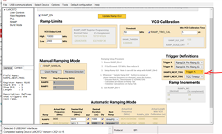
3rd option: Using automatic ramping mode as the first option indicate, but this time with the setting " trigger next ramp" = trigger 1. using external clock signal at the appropriate frequency to start the starting of each ramp.

I have tried this, and it shows the output signal response at the spectrum analyzer according to the triggering frequency. The problem here is that I can't figure out how to determine the incremental step of the ramping at each rising edge of the triggering signal, when I increase the triggering frequency the bandwidth of ramping decreases and vice visa. 

I need to determine the incremental step at each trigger rising edge, so I can know the bandwidth of the ramping signal.

  • Hi Bassam,

    The ramp engine in LMX2572 does not support flag. You may consider to use LMX2491 + external VCO. LMX2491 supports output flag signals as well as 8 ramp profiles, you can construct a more complicated ramp waveform.

    Since you need a MCU to program the LMX device anyway, maybe you can use it to generate a trigger signal to the ADC when you enable the RAMP_EN bit to start automatic ramping. This solution will simplify hardware. 

    I don't quite understand your last question, do you have an example to explain?

  • Hi Noel,

    I appreciate your response. I already got LMX2492EVM, but unfortunately, I couldn't get VCO that matches the evaluation board footprint and covers 3~ 4 GHz. TI suggests using 'CVC055BH-3600-3800", but it is out of stock. do u have any alternative solution to this problem?

    you can see the above picture which shows the details of the ramp setting. the important thing is the setting of 'RAMP0_NEXT_TRIG' = trigger1, which means that the next ramp (RAMP0) will start at the rising edge of the trigger1, this can be an external signal from MCU and it can synchronize the starting of the ramp with the ADC operation. it works gut with some issues:

    if I set the frequency of trigger1 to 1 kHz (1ms), then the time of each ramp should be 1 ms theoretically. because the Fpd=100Mhz, then the incremental step period of the ramp = 10 ns. the problem here is that I can't specify the amount of frequency change in each step, and thus can't guarantee it will sweep through the desired bandwidth (3600~3625)Mhz during 1ms.

    example: the step period =10ns and I want to know how many steps are required during 1 ms, which equals (1ms/10ns)/2=50000. ( divide here by 2 because 'RAMP0_Dly =1'. the required step size at BW=25 MHz is ( 25Mhz/50000=500 Hz) .

    the problem is that I can't guarantee the step size = 500 Hz, so it will match the calculation above because I don't have an option for that in TICs Pro GUI.

  • Hi Bassam,

    you may try MAOC-009261, this is a 7 - 7.9GHz VCO with divided by 2 output.

    Your calculation is correct. TICS Pro has calculated the step size of 500Hz for you, RAMPx_INC = 84. 

    One command to your configuration, you do not need to enable RAMP_TRIG_CAL as your frequency ramp range is just 25MHz.

  • Hi Noel,

    I appreciate your first response about MAOC009261. 

    the second part is quite unsure if it is true because there is no reference for that. if the ramping is automatic ramping with  " trigger next ramp" =TOC timeout, then it is true, but with  'RAMP0_NEXT_TRIG' = trigger1 is not sure. 

    the shocking issue is that when setting 'RAMP0_NEXT_TRIG' = trigger1, the response of the ramp in the spectrum analyzer is affected by both the triggering frequency and duration of the ramp value

    theoretically, the tow setting should match when the duration of the ramp value = 1000 or triggering frequency = 1 KHz, but, practically, they are matching only when triggering frequency approximately = 850 Hz (1.176 ms) as seen in the spectrum analyzer. Does it mean the VCO takes (0.176 ms) for the test process to start again from the beginning of the next ramp as it goes suddenly from 3625 Mhz to 3600 MHz?

    last question: how can someone measure the change of frequency with respect to time? What type of measurement tolls to use for that?