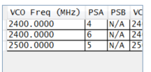
When the TICS Pro generates several frequency plans, and the difference is the order of dividers or a higher VCO frequency, is there benefit to selecting one vs another?
ie 2400/6/4 vs 2400/4/6 vs 2500/5/5 to achieve the same 100MHz?
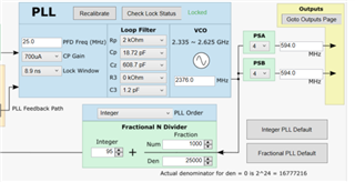
And secondly, do the loop filter values need to be touched from the defaults?
They only seem to vary when selecting Fractional or Integer defaults from what Ii can tell so far and do not match table 3 in the datasheet
And if so, how does one come up with setting for a value not in the table, such as 66MHz?