This thread has been locked.

If you have a related question, please click the "Ask a related question" button in the top right corner. The newly created question will be automatically linked to this question.

CDCE913-Q1: Pick to Pick and Amplitude of Y1,Y2 & Y3 value changing with respect to frequency.

Part Number: CDCE913-Q1
Other Parts Discussed in Thread: CDCE913

Hi Expert,

I have CDCE913 IC, configure through i2C.

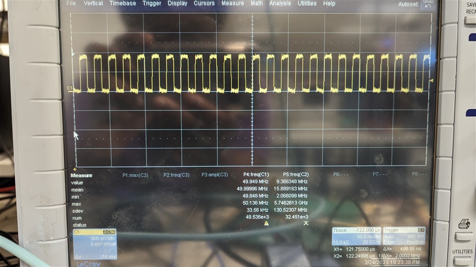
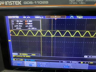
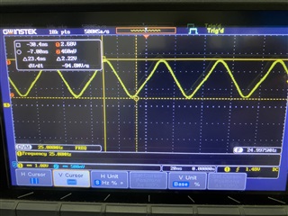
I am able to get desired output frequency but my amplitude and pick to pick voltage is changing when i am changing the frequency. Is it like that only or something is wrong. PFA image for reference.

  1. Default 25MHz frequency
  2. 50Mhz frequency with the following setting
    • M=4
    • N==40
    • Fin=25Mhz
    • Fvc0=250Mhz
    • Pdiv=5
    • P=1
    • Q=20
    • R=0
    • configuration register is
      • output selection Y1_7,FS1_7,SSC1_7 and Y2Y3_7
      • Y1_ST1 = 01, Y1_ST0 = 11
      • XCSEL = 0x09
      • SSC1_7 = 0b0111 / 0b001
      • Y2Y3_ST1=01, Y2Y3_ST0=11
      • SSC1DC = 0/1
      • VCO1_0_RANGE = 11 >175MHz
      • VCO1_1_RANGE = 11 >175MHz

Please help me out.

Waiting for your feedback.

--

Thanks & Regards,

Divyesh Patel

  • Divyesh,

    Is the oscilloscope set to a 50 Ohm impedance? Is there a termination resistor (18 Ohm to 22 Ohm) present on the output buffer of the CDCE913?

    The expected output voltage swings for different supply voltages are as follows:

    Vddo=3.3V --> Vpp=1.75V

    Vddo=2.5V --> Vpp=1.22V

    Vddo=1.8V --> Vpp=1.05V

    I can try your settings on an EVM tomorrow and see if I can reproduce this, but please let me know if the added termination resistance and scope settings resolve the issue.

    Thanks,

    Kadeem

  • Hi Kadeem,

    Thank you for your support.

    I have attached 22ohm termination resistor and checked with scope, but same result.

    Vddo=3.3V --> Vpp=1.75V

    Yes, we have CDCE913 IC which have 3.3V vddo, so vpp should be 1.75V.

    Waiting for your feedback.

    --

    Thanks & Regards,

    Divyesh Patel

  • Divyesh,

    I am seeing the following on my board with the same settings for 50 MHZ:

    Is VDDO still stable at 3.3V at the device pin when outputting at 50 MHz?

    If you use M=N=1 for 25 MHz output through the PLL, do you still see the 1.02 V swing? Or is it closer to 1.8 V?

    Can you share your schematic (k-samuel@ti.com)? It is unusual that your output is a sine wave - the output buffer should convert this to an LVCMOS output (my EVM has a square output for both a square and a sine input).

    Thanks,

    Kadeem

  • Hi Kadeem,

    Thank you for your helping me out.

    Actually, it might have an issue with our DSO, its capable of 100Mhz and we don't have 50 ohm impedance setting in the DSO and also probe is 60Mhz capable only.

    Next week i will check with another DSO and let you know.

    Till then please check schematic and let me know if correction is there.

    --

    Thanks & Regards,

    Divyesh Patel

  • Divyesh,

    Thank you - I will review this and have a response by Monday (PST).

    Please let me know once you have the results with the second DSO.

    Thanks,

    Kadeem