This thread has been locked.

If you have a related question, please click the "Ask a related question" button in the top right corner. The newly created question will be automatically linked to this question.

CDC3RL02: Questions about CDC3RL02‘s driving capability

Part Number: CDC3RL02

Hi team,

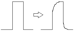
    The customers get questions about CDC3RL02.The CDC3RL02 manual describes that BUFFER can drive a wide range of capacitive loads.

    Q1.What is the output impedance of BUFFER?

    Q2 In their design, they will add a 50R+10pF filter part after the BUFFER output to solve the problem of EMI/noise floor, as shown in the figure below, does the low filter effect the driving capability? The low filter detail is shown in pdf of CDC3RL02 schematic.

CDC3RL02 schematic.pdf

    Q3. the customers use the RC to suppress harmonics. What are the differences between using RC and LC to suppress harmonics?

YOURS

NAN

  • Hi Nan,

    From the electrical spec, I estimated the output impedance is around 75Ω.

    I think it is better to design the RC filter with the IBIS or PSPICE model, they are available in ti.com.

    RC filter does not have a very sharp cutoff frequency point because the Q-factor is small. LC filter, especially being constructed with multiple stage LC components, has higher Q-factor and sharp cutoff point. 

  • Hi Noel,

         Thanks for your kind confirmation on output impedance and the pros & cons on RC filter and LC filter.

         As for Q2, I have installed the PSpice mode but I do not find the PSpice model of CDC3RL02 on ti.com. Could you please send me the link? I have downloaded the cdc3rl02.ibs and sent to customer.

        Or could you please help to simulate the RC parameter with CDC3RL02? Can you teach me how to judge the effect of the RC filter on output ability of CDC3RL02?

    YOURS

    NAN

  • Hi Nan,

    Sorry for the confusion, I am also confused by the product folder, we do not have PSPICE model for this part.

    We used to be able to use HyperLynx to do simulation with IBIS model, but due to license issue, we are not able do it anymore. 

    Output from the device is a square wave clock. The RC filter will attenuate the high frequency content, so the edge rate of the clock after RC filter will be smaller. 

  • Hi Noel,

         Really appreciate the your reply. 

    YOURS

    NAN