This thread has been locked.

If you have a related question, please click the "Ask a related question" button in the top right corner. The newly created question will be automatically linked to this question.

NA555: How to calculate the supply current about the NA555?

Part Number: NA555
Other Parts Discussed in Thread: TLC555, NE555

Hi  team,

      There is questions need to confirm

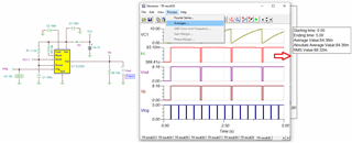
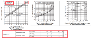
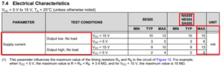
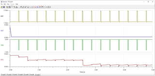
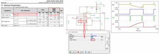
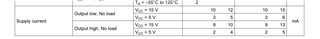
Q1: the customer want to know the supply current about the NA555. Here is how they use:Under normal circumstances, PIN 3 TRIG inputs high level, and PIN 4 OUT outputs low level; when TRIG inputs low level, OUT outputs high level and returns to low level after 3s. The voltage supply on vin is 5V. We only find the supply current without load.In such application, how to know the supply current with 5V?

YOURS

NAN

  • Hi Nan,

    how to know the supply current with 5V?

    For 5Vdc supply voltage, the operating current is approx. 6mA. Since you did not mention about the load at 5Vdc output, I am unable to tell you want peak current you may need. Also the overall supply current is a function of duty cycle at the output. You should be able to simulate it and determine the overall supply current, then you would need to add some overhead current for temperature variation. The max. output current is approx. ±200mA.  

    If you have additional questions, please let us know. 

    Best,

    Raymond

  • Hi Raymond,

          Thanks for your reply. I get to know that I_supply=I_out/duty cycle.

          After talking with the customer, the supply voltage is 15V. And the out pin would drive the NMOS.

          Here is the schematic from my customer.NA555_Schematic.pdf


          Could you please help me confirm how calculate the supply current? 

    YOURS

    NAN

  • Hi Nan,

        Could you please help me confirm how calculate the supply current? 

    I do not have NA555 PSpice model. I am going to use TLC555 as an example, and estimated the LDO's current and ratings in simulation. 

    After you run a complete simulation with an actual simulated load and supply voltage, you click on the Icc current of the Vcc supply (15Vdc as the example). 

    You click on Process --> Average --> the tool will prompt the Icc's Average Value --> In this case, the tool will prompt for Average Current Value of 84mA @15Vcc. So the LDO for the circuit should source a minimum 15V*0.084A = 1.26W at room temperature to run the TLC555 circuit. 

    TLC555 Current Calculation 03162023.TSC

    If Vcc of 15Vdc is generated from LDO, you need to size the LDO with a proper power --> you need to make sure that LDO is capable to source and sink the required currents per the LDO's Safe Operating Area (SOA) over temperature. From the LDO's SOA curve, you will get a minimum wattage of LDO required for the application. Then you double, triple or quadruple the minimum wattages (SOA) for the application as the safety considerations (You'd like to keep the LDO as cool as possible without overheating under the worst case operating conditions).  

    As a designer, you must consider not only the nominal operating conditions, but you also need to consider all fault conditions, misuses, prolonged extreme temperature operating conditions etc., so the LDO and the product is still able to operate under the extreme conditions. These operating conditions should come from the product's requirements.  In general, power sources are always oversized and overrated for a design. 

    We only find the supply current without load.In such application,

    Also, do not forget the xx555's supply current at Vcc = 15Vdc (under no load) vs. temperature. The simulation may not take into account the DC power requirements, but it should be small in general (15Vdc * 10mA = 0.15W without load).  

    If you have additional questions, please let us know. 

    Best,

    Raymond

  • Hi Raymond,

         Really appreciate your simulation based on TLC555.

         According to the  simulation, I find a way to evaluate the supply current almost.

         Iout =Vout/R4=6=9.16V/100Ω=91.6mA

         Considering the duty cycle, in the simulation, Iin=91.6*(T_high/(T_high+T_low))=88.02;

         I_without the load=0.3mA

         I_supply_current=88.02+0.3mA=88.3mA, which is really close to the absolute average 88.36mA;

         Based on the calculation above, we can calculate the supply current of NA555 roughly:

         With 15V supply, the V_out=14.3V;

         R_out=10kΩ

         Iout=14.3V/10kΩ=1.43mA;

         According to the datasheet, I_supply_15V_withou_load=9mA

         If we ignore the duty cycle, we can get the max of supply current:

         I_max_supply_15V_without_load=9+1.43=10.43mA.

         Could you please help to review my calculation to evaluate current supply of NA555?

    YOURS

    NAN

  • Hi Nan, 

    Here are some of my comments. 

         I_without the load=0.3mA

    Your calculation is ok for TLC555. This current figure is correct for the worst case analysis, which the TLC555 timer is a low power device.

       Based on the calculation above, we can calculate the supply current of NA555 roughly:

    NA555 consumes more power when there is no load, as shown in the table below.  You should use the worst case of 15mA at Vcc = 15Vdc. 

    Since I do not have NA555 PSpic model, the simulated current consumption is only applicable for TLC555 (low power timer). 

    Could you please help to review my calculation to evaluate current supply of NA555?

    Please try NE555 timer, which the current consumption may align more closely with NA555 device. 

    If you have additional questions, please let me know. 

    Best,

    Raymond

  • Hi Raymond,

         Thanks for your patient reply.

         After talking with customer, we decide to 30mA as max current supply.

         In addition, I make the simulation on NE555 as you told, and the schematic is followed from customer's design. But it seems something wrong with the simulation result.

         Could you please help me review the schematic of customer and debug the simulation?

    TLC555 Current Calculation 03162023 - autosave 23-03-20 10_00.TSC

    Much Thanks 

    YOURS

    NAN

  • Hi Nan,

    You would need to set trigger output voltage correctly, since this circuit is using15V supply rail. Also please check the triggering parameters.  

    TLC555 Current Calculation 03202023.TSC

    If you have additional questions, please let us know. 

    Best,

    Raymond

  • Hi Raymond,

         Really appreciate your simulation debug.

         I will send the simulation result and simulation.Any questions, I will share with you.

    YOURS

    NAN

  • Hi Nan, 

    Ok, please let us know if you have any additional questions. 

    Best,

    Raymond