This thread has been locked.

If you have a related question, please click the "Ask a related question" button in the top right corner. The newly created question will be automatically linked to this question.

LMK1D1204: No output

Part Number: LMK1D1204

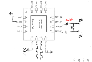
      I am testing the LMK1D1204 LVDS clock buffer on a breadboard to determine if it will work with a design. I am using a VDD of 3.3V and inputting a differential clock signal  from 0-2V yet the output is at a 0.5V steady state before the 0.1uF caps and 0V after the caps. Below is our configuration we are trying. At this moment we are not concerned about noise as this is just a simple “will it work” test. Is it possible that the floating inputs (IN1_P and IN1_N) are activating the fail-safe?

  • Hi Jonathon,

    A few thoughts:

    • Maybe IN_SEL is not fully connected? Try putting a tweezers or something on pins 1 and 2 and ensure the IN_SEL pin is shorted to GND
    • Is there a 10µF on VAC_REF0 (based on correspondence in a parallel channel)? If the AC bias isn't used then this pin can be left floating. 10µF is a bit much to put on this pin, it might be stressing the bias driver.
    • Is there a bypass cap from VDD to GND? I don't see it.

    I realize you may have already provided some feedback in a parallel channel to these thoughts, but it hasn't made its way to me yet... let me know if you've checked these things.

    Regards,

    Derek Payne

  • Checking those suggestions. 

    So I have the AC biased used by using a 0.1uF cap to GND. Would this cause the floating inputs(IN1) to affect the outputs of Out0?

  • Hi Jonathon,

    Could you tell if you were able to above suggestion? I will further assist with this if there is still an issue. If you can INSEL = 0 then IN1 should not cause problem. Its good to have a 1K pull down on unused inputs.

    Best,

    Asim