This thread has been locked.

If you have a related question, please click the "Ask a related question" button in the top right corner. The newly created question will be automatically linked to this question.

CDCE62005: the second stage of CDCE62005 couldn't lock

Part Number: CDCE62005

Hello,

 Our customer used two CDCE62005 for cascade application. But some of the board the second CDCE62005 couldn't be lock.

His description is as following:

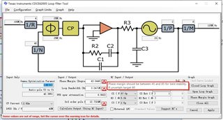
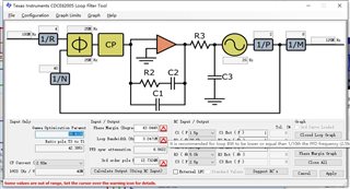
Our  circuit is fully referenced to TI's official 6678 development board, configured with an SPI interface controlled by an FPGA, and configuration files generated by official software;

We has   produced too many batch cards, but from last year began to fail, last year accumulated 2 cases, this year so far 7 more cases!

The failure to lock occurs only in the second stage; the failure to lock occurs in the second stage by reversing the front and rear chips of a faulty board.

The swap experiment eliminated the chip problem, non-new board eliminated hardware problems and software problems, the swap experiment and non-batch board card problems solved the welding problem, the next troubleshooting method is not clear.

Please tell us about the possible cause of the problem and its resolution.

Best regards

kailyn

  • Kailyn,

    I want to ensure that I understand the process correctly.

    1. The hardware setup is two cascaded CDCE62005 devices, with the output of the first device going into the input of the second device.

    2. There is a failure case where the second CDCE62005 is not locking to the input of the first CDCE62005 on some boards.

    3. Swapping the first and second boards results in a disappearance of the failure.

    Does the failure reoccur after any period of time after the swap is performed? Have you analyzed the output of the clock from the (former) first device in the failing cases, and how it compares to those systems that are operating normally? What is the clock configuration for both devices (is there a clock tree diagram that you can provide)?

    Thanks,

    Kadeem

  • Hi Kadeem,

    Thank you very much for  your reply.

    The hardware setup is two cascaded CDCE62005 devices, with the output of the first device going into the input of the second device.

    Yes。

    There is a failure case where the second CDCE62005 is not locking to the input of the first CDCE62005 on some boards.

    yes.

    Swapping the first and second boards results in a disappearance of the failure.

    No, Swapping the first stage of CDCE62005 and the second stage of CDCE62005 ,not swap the board, the failure still appear the second CDCE62005. 

    I will ask the customer wo provide the related configuration.

    Best regards

    kailyn

  • Hi Kadeem,

      The first stage  input frequency of CDCE62005 is 25Mhz, and output 100Mhz to connect the input of the second CDCE62005, it is the same connection of the official C6678 demo board.

    The fist stage configuration is as this:

    REGISTERS

    0 E9840320
    1 E9840321
    2 E9840302
    3 E9040303
    4 E9040314
    5 101C0B05
    6 90BE0F06
    7 FD0037F7
    8 80009cd8

    PORTS
    0 DD
    1 FF
    2 DF
    3 F9

    INPUTS
    PRI 100
    SEC 0
    AUX 25

    EXTERNAL COMPONENTS
    C4 1
    R4 1
    C5 1

    FPGA send the first PLL data of SPI:

    ctrl_data0 = 32'he9840320;
    ctrl_data1 = 32'he9020321;
    ctrl_data2 = 32'he9840302;
    ctrl_data3 = 32'he9040303;
    ctrl_data4 = 32'he9040314;
    ctrl_data5 = 32'h101c0b05;
    ctrl_data6 = 32'h90be0f06;
    ctrl_data7 = 32'hfd0037f7;
    ctrl_data8 = 32'h94be0f06;
    ctrl_data9 = 32'h94be0f06;
    ctrl_data10 = 32'h80008cd8;
    ctrl_data11 = 32'h80009cd8;
    ctrl_data12 = 32'h0000007e;

    The second CDCE62005 configuration is as following:

    REGISTERS
    0 EB040320
    1 EB040301
    2 EB060302
    3 EB0E0303
    4 EB060314
    5 000C0A75
    6 80BE03E6
    7 BD0037F7
    8 20009D98

    PORTS
    0 DD
    1 FF
    2 DF
    3 F9

    INPUTS
    PRI 100
    SEC 0
    AUX 25

    EXTERNAL COMPONENTS
    C4 1
    R4 1
    C5 1

    FPGA send the second PLL data of SPI:

    ctrl_data0 = 32'hEB040320;
    ctrl_data1 = 32'hEB040301;
    ctrl_data2 = 32'hEB060302;
    ctrl_data3 = 32'hEB0E0303;
    ctrl_data4 = 32'hEB060314;
    ctrl_data5 = 32'h000C0A75;
    ctrl_data6 = 32'h80BE03E6;
    ctrl_data7 = 32'hBD0037F7;
    ctrl_data8 = 32'h84BE03E6;
    ctrl_data9 = 32'h84BE03E6;
    ctrl_data10 = 32'h20008D98;
    ctrl_data11 = 32'h20009D98;
    ctrl_data12 = 32'h0000001F;

    Best  regards

    Kailyn 

  • Hi Kailyn,

    Thanks for the information, we will review it and get back to you as soon as possible. This is an old device that is not compatible with our modern configuration tools, so it will take some time for us to analyze it. We could take a quick look at the board schematics and layout too if the customer can provide them.

    Best,

    Evan Su

  • Hi Kailyn,

    Just an update on the situation, I have been trying to review the device configurations but have had problems installing the software used to configure the CDCE62005 on my computer. I tried manually decoding the register configurations but it took too much time, I will talk with our software team to see what they can do. In the meantime a colleague suggested that if two identical clock generators are cascaded, there could potentially be problems if their loop filters are configured the same or similarly. Do you know if this is the case here?

    Best,

    Evan Su

  • Hi,

    We use "Suggest RC's" function to set Loop Fiter parameter. The results of  two identical clock generators are different.

    But the results have warning signs and we have no idea to clear them.Is there any problem with these warming signs?

    Best.

    Huang Feng

  • Hi Huang,

    Can you provide us a screenshot or write in text what the warnings are?

    Best,

    Evan Su

  • Hi Huang,

    Thanks for the information. The warnings seem to be related to the stability of the loop filter. Sometimes they can be ignored but in this case we are investigating the stability of the cascaded devices so we should examine them. I will look for a team member with more experience on loop filter design and update you soon.

    Best,

    Evan Su

  • Hi Huang,

    We should try to fix the warnings in this case, here is a summary of recommendations:

    • Adjust the component values until the warnings about phase margin, loop bandwidth, and poles are resolved. For example, the 3.2471 MHz loop bandwidth is higher than normal for this device.
    • The two cascaded devices should not have the same loop bandwidth to lower the risk of spikes being amplified and causing the second device to be unstable. The second device should have a larger loop bandwidth than the first one.

    Let us know if this helps.

    Best,

    Evan Su

  • Hi Evan,

    The bad chips seem work well when change the LF parameter. Now we have another problem:

    1. Do we have to change the parameter of the chips whitch are using old parameter and pass the testing?

    2. If we need to change the parameter,  is it necessary to do all testing again?

    What about your suggest?

    Best,

    Huang Feng

  • Huang,

    I would recommend changing these so that the loop filters are stable for these devices.

    I would advise retesting a subset of the boards to ensure that there are no issues with the new loop filter.

    Thanks,

    Kadeem