Hello!
I want to use a CDCM7005 together with VCO, a having sinusoidal output (0 dBm or +10 dBm). What typical connection VCO to a differential LVPECL CLK CDCM7005 input?
This thread has been locked.
If you have a related question, please click the "Ask a related question" button in the top right corner. The newly created question will be automatically linked to this question.
Hi Yuha,
There are several aspects to consider when connecting a sine wave to the CDCM7005 one is the rising/falling time max of 3ns. Normally the sine wave has slow edges.
Second point is the amplitude you mentioned 0dBm and 10dBm over. If 50 Ohms used then it is 0.224V and 0.707V respectively. The CDCM7005 has a min input for the VCXO of 500mV. So you would need to increase the 50 Ohms to a higher value to guarantee that it is always above 500mV.
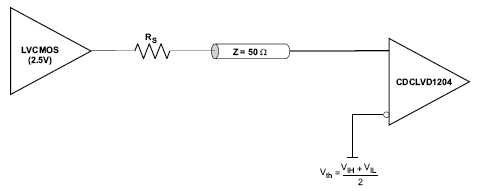
Finally, the way to connect a single ended signal to a differential input is:
Hope this helps. Please let us know either way.
Regards,
Justo
Thanks, Justo.
It would be desirable to note:
Justo said:There are several aspects to consider when connecting a sine wave to the CDCM7005 one is the rising/falling time max of 3ns. Normally the sine wave has slow edges.
- are assumed a range of used frequencies: 260-320 MHz, therefore rising/falling time less than 3ns (period sine signal - 3.1-3.8ns);
Justo said:Second point is the amplitude you mentioned 0dBm and 10dBm over. If 50 Ohms used then it is 0.224V and 0.707V respectively. The CDCM7005 has a min input for the VCXO of 500mV
If 0dBm/50 Ohms used then it is Vrms=0.224V and Vpeak-to-peak = 0.632V.
If 10dBm/50 Ohms used then it is Vrms=0.707V and Vpeak-to-peak = 2V.
The CDCM7005 has a input amplitude LVPECL (Vvcxo_in - (-Vvcxo-in)) = 0.5 - 1.3 V, therefore used 0dBm/50 Ohms sine signal - guaranteed probably. But used 10dBm/50 Ohms sine signal probably only after attenuation.
I am right?
Whether probably such connection at the set parametres?
Hi Yuha,
260-320MHz sine wave it is okay then.
If you can guarantee 0dBm min then you should be okay. The CDCM7005 will work even if the input is less than 500mV p-p but the AC specs can be a little bit worse. 2Vpp should be attenuated as you mentioned.
Regarding the schematic it looks good: 50 Ohms input impedance and CLK- is centered at Vdd/2. It will work.
Please let us know if you have any other question.
Regards,
Justo
Can I feed 800 MHz sinusoidal to one of the input (primary) to CDCE62005 as external clock with the same circuit at input side and to the secondary input from onboard oscillator?
No problem. Do it in the same way you suggested for the CDCM7005. Although it is single ended it would work as differential with that circuit.
Take into account the max frequencies in page 18 of the datasheet for internal division.
Regards,
Justo
Hello Bhupesh,
there is no circuit attached. Can you please send it?
Regards,
Justo
Hello Bhupesh,
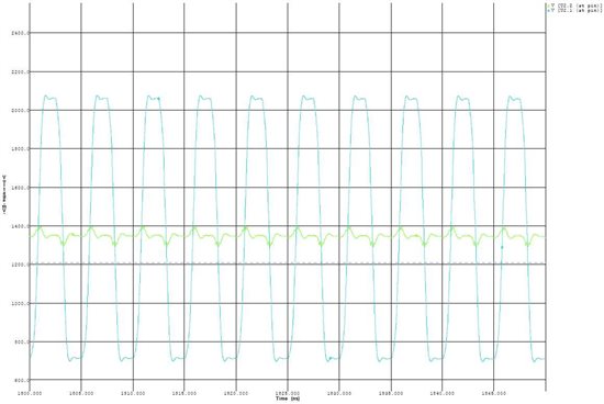
Please find attached one simulation for the circuit decribed above by Yuha.
The inputs to the differtial input are converted to differential and they do not have the same phase since the negative input is a constant, therfore the input are not in phase. The resistors are there to provide a constant voltage (centered) to one input and to pass the single ended clock in the other.
The figure shows green for one input, almast constant. Blue the other input, clock signal with good amplitude.
Please let me know if you have any other question.
Regards,
Justo