This thread has been locked.

If you have a related question, please click the "Ask a related question" button in the top right corner. The newly created question will be automatically linked to this question.

LMX2581EVM: Phase shift between input reference and output

Part Number: LMX2581EVM
Other Parts Discussed in Thread: LMX2581, CODELOADER

Dear Specialists,

My customer is testing LMX2581EVM.

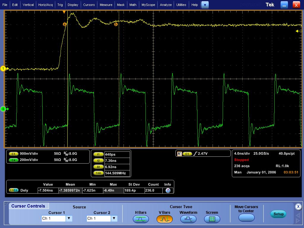
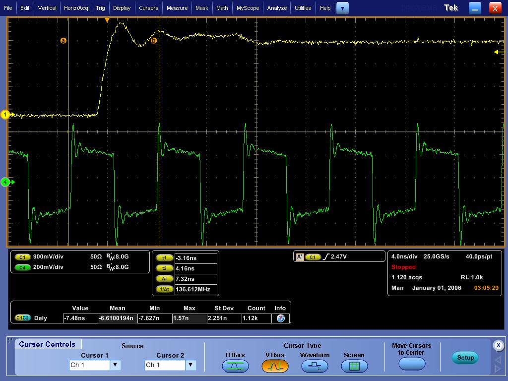
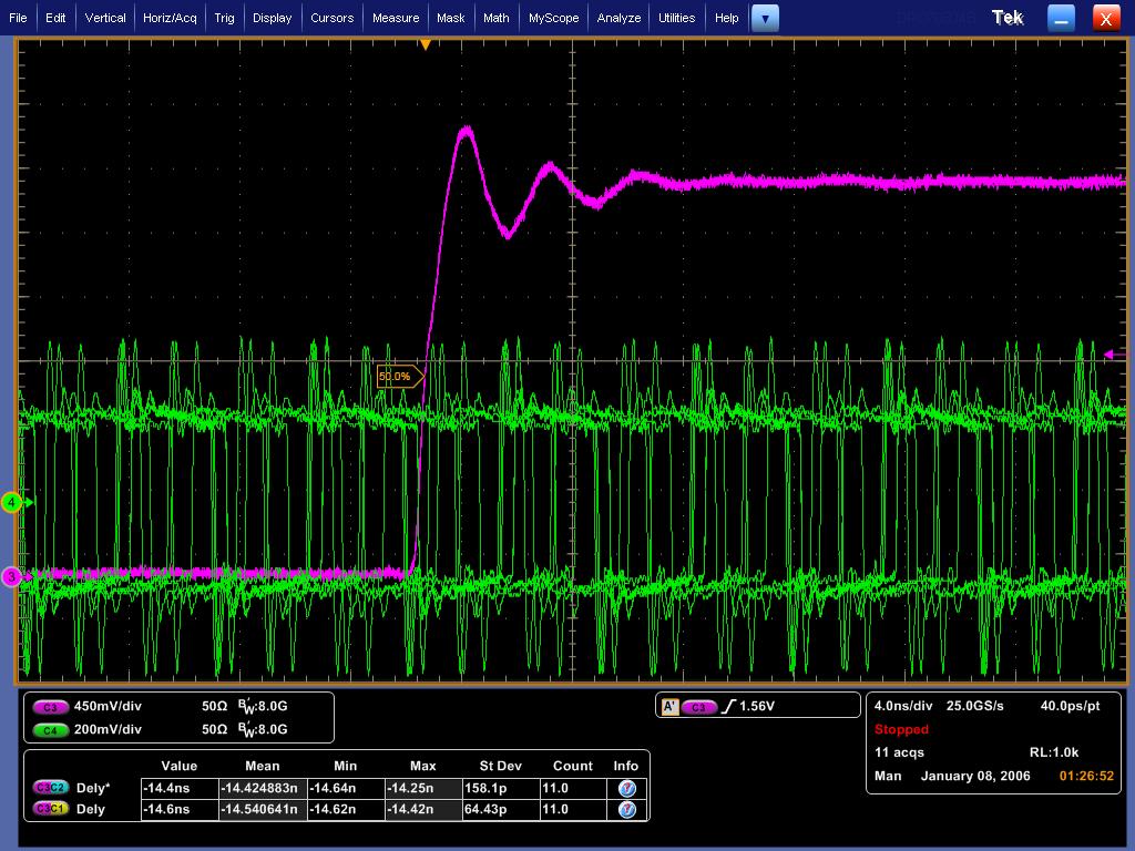
He confirmed phase shifts between input reference and output.

The phase shift is not constant value, different value at the moment to moment.

Could you please see three attached files.

(1) is this phenomenon normal, or not?

(2)If so, how much is the maximum phase shift?

(3)Why does the phase shift happen?

He wants to design a perfect synchronous timing circuit, he has to know how much is phase shift in detail.

I appreciate great help.

Best regards,

Shinichi


  • Shinichi,

    Whenever there is division involved, a phase shift can be created.  For instance, if you divide by 2, there are two possible phase that are 180 degrees apart. 

    The LMX2581 has a divider after the VCO and this can produce a random phase shift.   This can also come from the R divider.

    TThere is  a zero delay mode that can be used to put the VCO divider in the feedback path to use or zero delay

  • Dear Dean,

    Thank you for your reply.

    I understand the a phase shift can be created.

    So I'll make the customer to use a zero delay mode and see datasheet P.20 of 8.3.10 0–Delay Mode.

    I appreciate your great help.

    Best regards,

    Shinichi

  •  Dear Dean

    The customer tried to zero delay mode, but the result was not desired.

    When he used zero delay mode, phase shift is unstable.

    If zero delay mode is off, phase shift is stable.(the value is depended on the power up timing)

    Could you please see attached file.
    You can see 144MHz(green line) is not stable compared to 12MHz reference.

    The setting is followed by the datasheet.

    Procedure
    1. If N is not divisible by VCO_DIV, reduce the phase detector frequency to make it so.
      ※please see codeloader setting,N=168 is dividable VCO_DIV14, it is not a problem.

    2. Program as normal and lock the PLL.
      ※It programed as usual.

    3. Program the NO_FCAL =1.
      ※It is checked NO_FCAL on the Codeloader.

    4. Program 0_DLY = 1. This will cause the PLL to lose lock.
      ※Codeloader上でIt is checked ZERO_DELAY on the Codeloader.

    5. Program the PLL_N value with PLL_N* / VCO_DIV, where PLL_N* is the original value.
      ※He thinks it is executed if N is not dividable VCO_DIV on procedure 1.

    6. The PLL should now be locked in zero delay mode.

    Could you please advise what is wrong?

    I appreciate your great help.

    Best regards,

    Shinichi

    Codeloader.pdf

  • Dear Dean

    How is the condition?

    I'd like to answer to the customer.

    Could you please advise him what to do?

    I appreciate your great help.

    Best regards,

    Shinichi

  • Shinichi-san,

    I see the following from the customer settings

    Fosc=12MHz

    Fpd=12MHz

    Fvco=2016 MHz

    PLL_N = 168

    So to lock this, the customer would lock as normal.  Then set NO_FCAL=1.  Then enable zero delay mode.  Then set PLL_N=12, which would mean the VCO frequency would look like 144 MHz in Codeloader and would be red, although this is correct.  Then it should lock.  Are you programming PLL_N=12?

    Regards,

    Dean

  • Dear Dean

    Thank you for your reply.

    I understand the last PLL_N programing is necessary.

    I'm going to send your advise to the customer.

    I appreciate your great help.

    Best regards,

    Shinichi