This thread has been locked.

If you have a related question, please click the "Ask a related question" button in the top right corner. The newly created question will be automatically linked to this question.

CDCM7005: Scope between CPout and Vtune in VCXO

Part Number: CDCM7005


Hi Team,

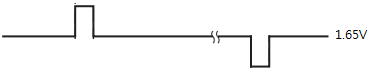
I saw abnormal charge pump voltage scope like as below.

PDF is 80kHz and matched with scope peak period.
When I measured in EVM, CP voltage scope was different.

In my understand, CP voltage level should be stable when PLL lock. (input 61.44MHz for EVM)

#1 is CDCM7005 PLL unlocked and #2 is CDCM7005 PLL locked correctly.
Frequency is same, but peak amplitude a little bit different.
Why customer board CP voltage level scope is not same as EVM even if PLL locked correctly?
Thank you.

Best Regards,
Jade

  • Hi Jade,

    Is Y4 a VCXO? Is the period of the "sawtooth" signal 80kHz? This looks to me that the problem is the input impedance of the Vc pin of the VCXO is too low. As such, there is a serious leakage current when the charge pump is in the off state.
    There are couples of way to resolve this problem:
    1. Use a VCXO with higher Vc pin input impedance
    2. use a higher fpd (around 1MHz)
    3. use a higher charge pump current
  • Hi Noel,

    Input frequency : 10MHz
    VCO frequency : 30.72MHz

    In this case, maximum PDF freqeuncy is 80kHz and cannot increase up to 1MHz.
    Also used 3mA charge pump current which maximum from CDCM7005.

    VCO minimum frequency control input impedance is only 10kohm and they have to use more higher input impedacne VCO. I know this point.
    However is there any workaround to improve the current issue?
    Thank you.

    Best Regards,
    Jade
  • Hi Jade,

    10kohm is exceptionally small, I encourage the customer to find and use a higher impedance VCXO.
    In this case, maybe we can redesign the loop filter such that the capacitors are larger. This may reduce the discharge rate.
  • Hi Noel,

    Please refer below configuration for customer configuration.

    Input : 10MHz
    VCXO : 30.72MHz
    PDF : 80kHz (highest frequency)
    CP current : 3mA
    Loop filter BW : 1kHz

    They changed loop filter BW to 30Hz from 1kHz and they saw stable DC voltage at Vtune pin but amplitude was different between two samples.

    1. Unlock sample(abnormal) : CP voltage level around 2V but looks like DC and PLL locked
    2. Lock sample(normal) : CP voltage level around 1.7V and looks like DC and PLL locked.

    Question.

    Why narrow BW impact to CPout scope and impact to locking of PLL?
    Would you explain the symptom with narrow loop filter BW?
    If customer measure voltage at CPout without external loop filter, they can see PWM voltage signal scope like as below, right?


    Thank you.

    Best Regards,
    Jade

  • Hi Jade,

    I think with 30Hz loop filter, the loop filter capacitors are bigger, so they can extend the discharge process longer.
    Your diagram is the charge pump response and the y-axis is current. When the charge pump is turned ON, it will either sink or source current. So if you really want to measure it, you should use a current meter or current probe.