This thread has been locked.

If you have a related question, please click the "Ask a related question" button in the top right corner. The newly created question will be automatically linked to this question.

LMK04826BEVM: LMK04826 not locking

Part Number: LMK04826BEVM
Other Parts Discussed in Thread: LMK04826

Hi,

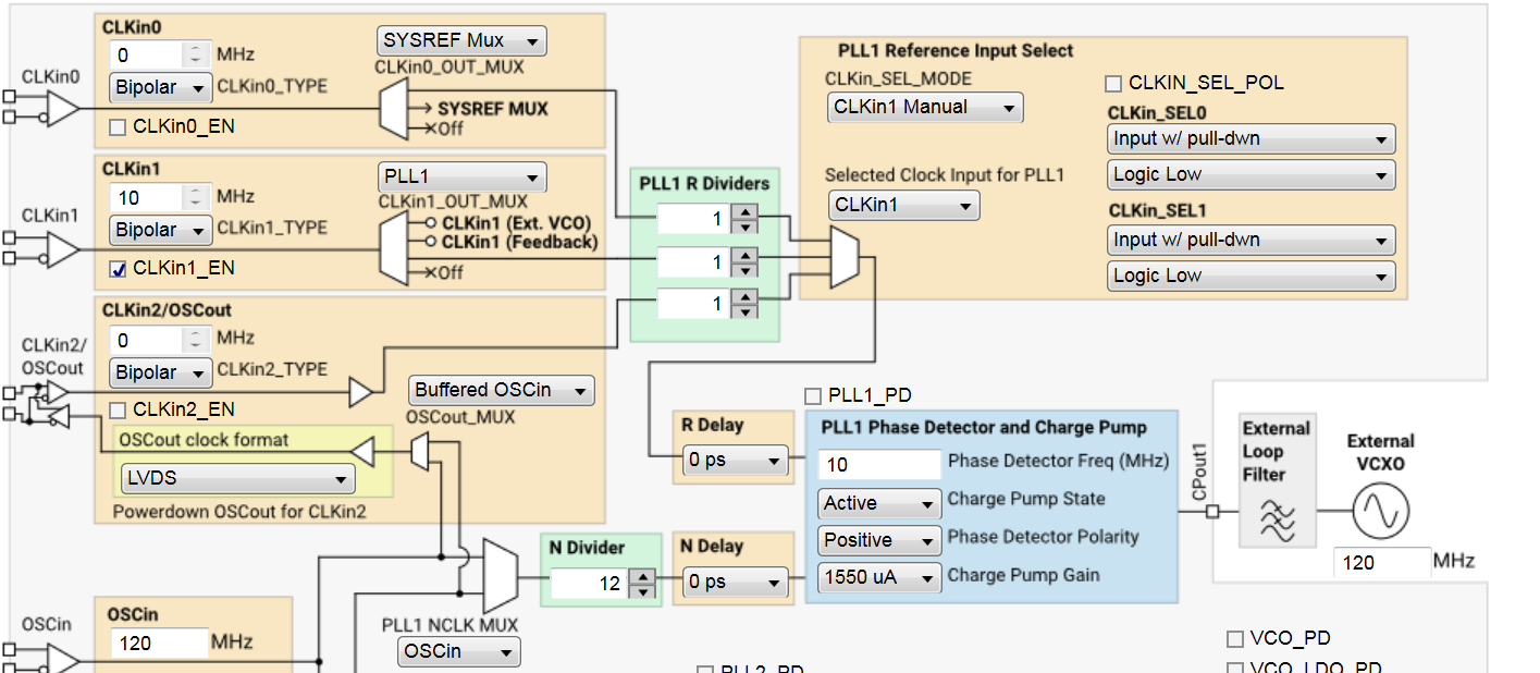
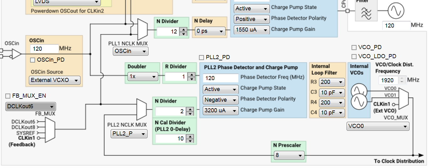
First, I have replaced VCXO with 120MHz one with Crystek CVHD-950 VCXO from 122.88MHz mount and it worked very well showing ~130fsec at 192MHz output. Now, I have replaced VCXO again with Transko TV53A VCXO, 5x3.2mm sized (small foot print) to check my real application with small footprint but somehow it does not lock at all. I have used the same setup file for TicPro for all 120MHz configuration but one vendor worked but the other not. can you check what is going on? I will ultimately will use Transko's TSMV5 5x3.2mm VCXO but it takes time to be designed and delivered. So, in temporary I tried to use TV53A. I have found TV53A input impedance is very high 1Mohm while CVHD-950 has 51kohm. I wonder if this mattered.

In Summary:

1. OSCin: replaced 122.88MHz VCXO with 120MHz VCXO (Krystek CVHD-950) on EVB. working great.

2. OSCin: replaced Kystek 120MHz VCXO with Transko TV53A (5x.32mm foot print). no locking

3. OSCin: ultimately will use Transko TSMV5 (5x.32mm foot print) later once delivered.

3. CLKin1: Firefly-II OCXO was used for 10MHz for all time.

Please let me know any suggestions to try. I have attached PDF files for datasheets of all mentioned parts above.

Thanks

FF-IIA_low-g_DOCXO_specs.pdftv53a.pdftsmv5.pdf

  • Hello Youngho,

    You asked about the input input impedance. There is no issue. Higher is better. Interestingly in the past I've measured the CVHD-950 and found it to be closer to 1 Mohm than 51 kohm.

    When you say it does not lock at all, can you advise if it is PLL1 , PLL2, or both which are not locking?

    Have you confirmed an output clock from the TV53A? Is it nominally the frequency you expect?

    Note that the TV53A says it is availible in CMOS, LVDS, and LVPECL output formats. Are you using the CMOS version as CVHD-950? If you're using the LVPECL version, you would need to provide some emitter resistors to get an output clock. Total failure of OSCin clock would cause PLL1 & PLL2 to be unlocked.

    What other debugging have you done? If you set the status output pins to PLL1 N/2, PLL1 R/2 you can see what the PLL is getting... if they have a fixed phase, they are in lock. You can do this also for PLL2 N/2 and PLL2 R/2. For both cases you should see half the phase detector frequency.

    73,
    Timothy
  • Hi Timothy,

    Both PLL1 and PLL2 are not locked based on lock LED off on the board.

    I have monitored TV53A output through OSCout port found frequency about 120.0005MHz and start to drift down slowly near 119.9995MHz within 10 min. The vendor said output current of the TV53A is about 8mA. I forgot to say, I also have changed R4 and R61 resistor values to 210ohms to split to half rather than a third for ~8mA. Also, I have probed output pin of the TV53A found ~2.9Vpp between TC53A output pin and C4(33pF), ~2.6V between C4(33pF) and R4(210ohm), and 0.75Vpp between R4(210ohm) and R61(210ohm).  Strangely, with scope I measured ~0.75Vpp rather than the half of 2.6V. Still this is good input range of OSCin of the LMK04826, I believe. i also probed Vtune pin at TV35A and found ~1.651V.

    I use output type of LVDS at DCLKout10 port. The setup was fine with CVHD-950 and used the same setup for TV53A.

    output frequency I obtained was ~193.1MHz rather than 192MHz at DCLKout10 port. 

    Do I need more current at this voltage divider network? Please advise what to do next.

    Thanks

  • Hello Youngho,

    I expect the reason for the lower than expected Vpp is due to RF mismatch. By altering R61 away from 51 ohms, you no longer have a 50 ohm termination and reflections will cause unexpected voltages.

    To confirm the input signal. Please program the output status pins to PLL1 N/2 and PLL2 R/2 to see the divided output of the OSCin signal. You should expect to see half the phase detector frequency.

    I also recommend programming for PLL1 R/2 and PLL1 N/2 and compare the waveforms. They should ideally be locked in phase. But if not, this can give you a hint to what is going on / which signal is not working. Same goes for PLL2 R/2 and PLL2 N/2. Please check these outputs and advise.

    73,
    Timothy
  • Hi Timothy,

    I have PDF 10MHz for PLL1 and 120MHz for PLL2. It looks like I can't attach TiCPro setup file but here is a screen shot for setting.

    About PLL1 R/2 and PLL1 N/2, I measured 15MHz with PLL1 N/2 and 5MHz with PLL1 R/2. They are not the same either.

    About PLL2 R/2 and PLL2 N/2, I measured 65MHz with PLL1 N/2 and 60MHz with PLL1 R/2. They are not the same frequency either.

    I will replace R61 and R4 with 50ohm resistors to get the right 50 ohm impedance and will see if this makes difference. But, if you observe something to try, please advise.

    Thanks

  • The resistor values changed to all 50ohm worked out. I think there were reflection due to the mismatch. Now PLL1 R/2 and PLL1 N/2 measured to 5MHz of PDF, which it should be. Thanks,