This thread has been locked.

If you have a related question, please click the "Ask a related question" button in the top right corner. The newly created question will be automatically linked to this question.

LMK03806BEVAL: LMK03806BEVAL Evaluation Board Not Giving Out Clocks Correctly

Part Number: LMK03806BEVAL
Other Parts Discussed in Thread: USB2ANY, LMK03806, USB2ANY-UWIRE

LMK03806BEVAL Evaluation Board Not Giving Out Clocks

Hi anyone who may concern,

Recently I am using LMK03806BEVAL evaluation board. I am using TICS Pro in Windows 10. Connect the USB2ANY with USB interface of the laptop and uWire interface of LMK03806BEVAL.

However, only CLKout6/6* (1.2V Single-Ended Amplitude) and CLKout8/8* (0.4V Single-Ended amplitude) give 100 MHz clock as shown in Fig.1. The others clock outputs cannot give out clocks no matter how I change the settings.


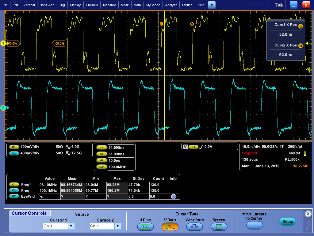
Fig. 1 The output of CLK6(Bottom Row) and CLK8 (Top Row)

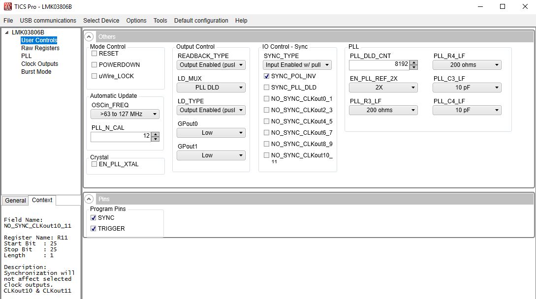
My setting is as the following Fig 2~5 (Most of them are default settings). Before the setting, I choose default configuration "100MHz XO/TCXO Reference". After the setting I checked write all the registers. If the board is working correct, the output waveforms should change the speed to 1.2GHz and 200MHz respective as configured in Fig. 5. However, the waveforms are always the same as the intial waveforms. They does not change at all. I tested other outputs. All are no signals except the oscillator outputs.

Therefore, can anyone help give some suggestions about how to make the evaluation board function well? 

Your help is very appreciated!

Best Regards, 

Wu Han

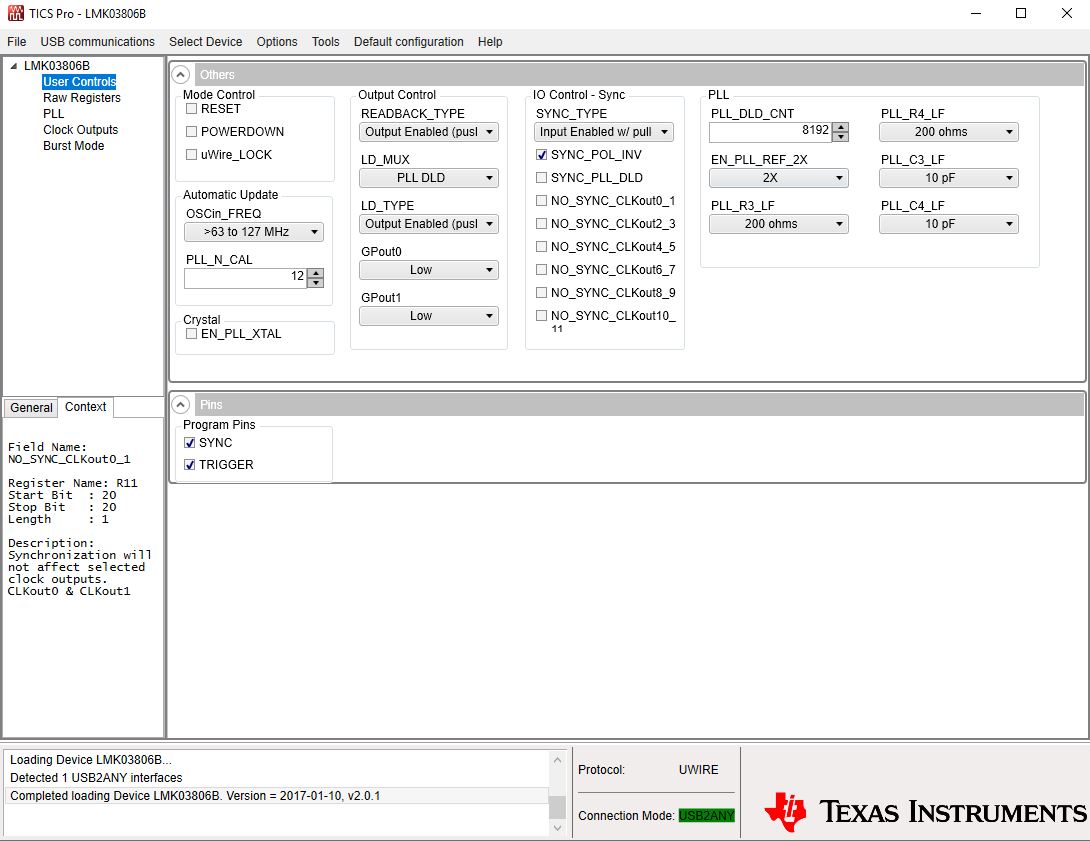
Fig. 2 User Controls

Fig. 3 Raw Registers

Fig. 4 PLL

Fig. 5 Clock Outputs

  • Thanks for posting on E2E. I have assigned your post to the responsible engineer. He will respond to you soon.

    Kind regards,
    Lane

  • Hello Han,

    It appears the programming is taking no effect and you are seeing start-up clocks.  The LMK03806 should have come with a USB2ANY-uWIRE board.  You should configure this board with jumpers as illustrated in the USB Communication --> Interface window.  Then connect it between the USB2ANY and the EVM for proper programming.

    73,
    Timothy

  • Hello Timothy,

    Thanks very much for your suggestions.

    I opened the interface. There are some jumpers as shown in Fig. 6 (Looks the default connections are the same as the manual shown for LMK03806B). And I cannot moving them in the user interface. May I know how to operate the jumpers (do I need to open the box of USB2ANY and connect the physical jumper as shown in Fig. 7 ?) and what is the correct connections between USB2ANY and EVM (Is it the same as shown in the Fig 6)?

    Best Regards,

    Wu Han

    Fig 6 User Interface

    Fig 7 USB2ANY

  • You would have a physical board as illustrated with the jumpers connect between the USB2ANY and the EVM.  If you do not have this board, then the SPI signals will come out on the wrong pins and you would not be able to program.

    I think you do not have this USB2ANY-uWIRE board.  Correct?

    73,
    Timothy

  • I only have USB2ANY and LMK03806BEVAL board. May I know where can I purchase this USB2ANY-uWire board?

    Thank you.

    Best,

    WuHan

  • Hi Timothy,

    I searched on the websites. There is no vendor who can sell USB2ANY-uWire board. Could you give suggestion about where I can purchase this board?

    Thanks you very much.

    Best Regards,

    Wu Han

  • Hello Wu Han,

    I suggest cutting the 10 pin cable and making connections as follows:

    USB2ANY    <--->  LMK03806B

    4   <-- Data -->  2

    8   <-- Clk  -->  4

    2   <--  LE  -->  6

    6   <-- GND -->  9

    You can add if desired:

    9 <-- SYNC --> 1

    Note SYNC can be manipulated by programmed SYNC_POL_INV while keeping pin state fixed if you don't connect.  Be aware that SYNC asserted will prevent output clocks if the NO_SYNC bits are not set.

    73,
    Timothy

  • Hi Timothy,

    Thanks very much for the suggestion. I have three questions about SYNC.

    Question 1:

    About SYNC, if I do not connect 9<--SYNC-->1, SYNC_POL_INV is checked as shown in the following figure. Is this setting right?

    Question 2:

    And if I connect 9<--SYNC-->1 and want CLKout0_1 to give out clocks, should I uncheck SYNC_POL_INV and check the corresponding NO__SYNC_CLKout0_1?

    Question 3:

    What is the function of SYNC_PLL_DLD? When should I check this option?

    Your answers are pretty appreciated!

    Best Regards,

    Wu Han

    IO_Control SYNC

  • Hello,

    From datasheet 8.6.7.3 for SYNC_PLL_DLD: "By setting SYNC_PLL_DLD a SYNC mode will be engaged (asserted SYNC) until the PLL locks."  Set as desired for your application.

    From datasheet 8.6.6.2 for SYNC_POL_INV: "Sets the polarity of the SYNC pin when input. When SYNC is asserted the clock outputs will transition to a low
    state." with the table 0 = SYNC is Active High, 1 = SYNC is Active Low.

    The EVM has a 27 k pull-down on SYNC pin (as apart of a voltage divider for usage with 5 V LPT port).  With SYNC_TYPE programmed = 0 (Input) or = 1 (Input with pull down).  Then with no connection of SYNC pin.  Then SYNC_POL_INV must be set = 0 to allow outputs.

    73,
    Timothy