This thread has been locked.

If you have a related question, please click the "Ask a related question" button in the top right corner. The newly created question will be automatically linked to this question.

LMC555: LMC555 output capabilities, et al

Part Number: LMC555
Other Parts Discussed in Thread: TLC555, TLC556, SA556, NA556, SE556, NE556

The TLC555 shows dfferent output current capabilities, for source (10mA) and sink (100mA).  The LMC55 show only one (100mA).  Does this mean the LMC555 can source 100mA while the TLC555 can't?

Is the LMC555 a later design than the TLC555?

Will there be a LMC556 dual timer?

Finally a nit typo: the general layout shows a 0.001uF control pin capacitor.  But all of the examples show 0.01uF

  • Hello Rod,

    The LMC555 source current and sink current vary with supply voltage and sink drive is more powerful than source. The TLC555 is the same in this regard. Look at the Electrical Characteristics tables for VOL and VOH specifications and the tested current levels. The control capacitance is not critical, higher values will reduce noise better but it will take longer for the control pin voltage to rise to its final value (of 2/3 VDD) after power up.

  • Rod,

    We have dual timers; TLC556 is nearly the same as two LMC555 timers. 

    We also have bipolar dual timers, NA556, NE556, SA556, SE556 which vary by temperature range.

     The bipolar timers have strong source current drive.

  • I was really questioning the datasheets.  The TLC555 is very clear on the difference between output source and sink capabilities.  The LMC555 is not.  Maximum ratings say I_out is simply  ±100mA.  But in Electrical characteristics for V_ol at 12v it shows 50mA and at V_oh it shows -10mA (the minus 10 for source is confusing).  I was clarifying if the max of 100mA is still valid, or can the output source current = 30mA (positive???) with no detrimental effect.

  • Rod,

    I agree that the TLC555 AMR table has more details and separates source drive from sink.

    Output high conventional current from a device into a load is often specified as a negative value. The original reason is based on loads and power sources. I think of it in a "I'm the test equipment" mindset. The LMC555 source current flows in to me so I call it negative because I'm absorbing power. For sinking, current flows from me to the LMC555 so I'm suppy power and I call that positive current. 

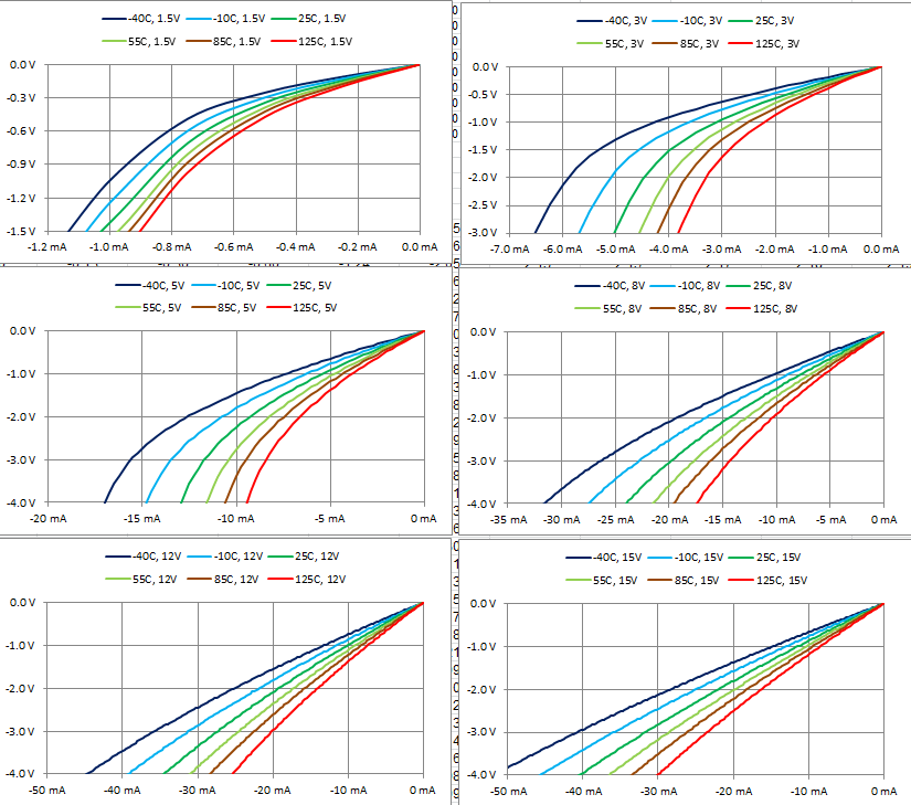
    At some some supply voltages, the LMC555 will not produce 30mA at all. At higher supply voltages, 30mA could flow but there is significant voltage lost. (VDD-VOUT)

    Here are sample results. Other samples may be stronger or weaker.

    I do not recommend 30mA source current.