This thread has been locked.

If you have a related question, please click the "Ask a related question" button in the top right corner. The newly created question will be automatically linked to this question.

TRF3765: TRF3765 Low Power

Part Number: TRF3765

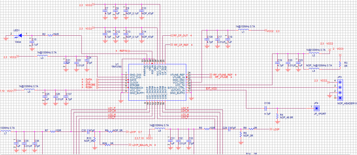
Below is I used the TRF3765 schment,the maximum output power of Lo is only - 28dBm,what is the reason about it?
  • Song:

    Based on your input I assume that the device is programming to the proper frequency and the output signal is too low.  Typically I would focus on the output network.  I cannot see the entire output network but it looks like you are mimicking the TI EVM approach.  Ensure that you are biasing both the positive and negative ports of any given channel.  I also see some series resistors on the output and cannot tell the values exactly.  Just make sure you are not introducing a voltage divider loss.

    If the output network is good.  Double check the SPI programming on the channel enable/disable.  You may have inadvertently disabled a given channel's output buffer which will result in low output power.

    --RJH

  • hi,Hopper:

           Updata some information:

    1.The attachment  is the full schment, please help check;

    2.I only want to use the TRF3765 to proce a LO signal for mixer HMC218B;

    3.If I can only use the positive ports LOP1, not use the negative ports LOM1, I made a compatible design;

    4.what is the mean about” Ensure that you are biasing both the positive and negative ports of any given channel”;


    5.If the TRF3765 pin18(EXTVCO_IN)must have a input signal;


    6.Below is my command for SPI, Please check for errors:

       /overlay/upper/usr/sbin/a.out w 54100289     //reg 1

       /overlay/upper/usr/sbin/a.out w b             //reg3

       /overlay/upper/usr/sbin/a.out w 800E00C       //reg4

       /overlay/upper/usr/sbin/a.out w 1D8E968D     //reg5

       /overlay/upper/usr/sbin/a.out w C671100E     //reg6

       /overlay/upper/usr/sbin/a.out w 88A0866A     //reg2

    After this commands ,used the signal analyzer I can see a signal level is about -28dBm

  • Song:

    I reviewed the schematic only related to the output network.  You cannot bias just the OUTP port and leave OUTM port unconnected.  Even if you do not want to use that port, you still need to bias it similarly to the OUTP port.  After the coupling cap, provide 50 ohm load to ground.

    Per question 5, you do not need to inject a signal on the EXTVCO.

    I did not explicitly check/review the programming, but I just wanted to ensure that you are enabling the buffer on LO port 1.  The buffer for LO ports 2, 3, 4 should be disengaged if those are not being used.

    --RJH

  • hi,Hopper:

              Thanks for your reply.

               I will process the Lo output as you say。

              About the "The buffer for LO ports 2, 3, 4 should be disengaged if those are not being used." ,how do I separate the unused LO ports.

              I measure the other ports 2,3 4 all have same signal level, so I guess the other ports are not separated.

    thanks!

  • Song:

    When I say disengaged, I mean that the SPI programming turns off the buffer for those channels.  Since you are not using those channels, it is a good practice to turn off the buffers internally in the device.  In practice, with no bias on those channels, they will effectively be off too.

    --RJH

  • hi:

           1.I only used the LO1,but why I can test the signal on the other LO channels,the LO2,3,4 have the -28dBm signal level too;

           2.How can I turn off the buffers internally in the device.

    thanks!

  • hi:
            1.Which registers affect the max power;

            2.If the Fpfd affect the power?

            3.If the Loop filter affact the power

    thanks!

  • 1.Which registers affect the max power;

    RJH>> I am referencing Register 4, bits 12-15.  These are the power-down bits for each channel.  If you have inadvertently powered-down buffer 1 then you will see a significant drop in output power.

            2.If the Fpfd affect the power?

            3.If the Loop filter affact the power

    RJH>> No to both.

  • hi:

          1.I set the Register 4, bits 12-15 to 1111,the LO1 output power is -23dBm,set to 0001 the output power is -33dBm,set yo 1110,the output power is -27dBm,

            If the test result is normal?

           2.If we have other Register need to set?

    thanks!

  • Song:

    An output power of -23 dBm is too low.  If you definitively know the frequency is locking on target, then the SPI programming must be correct.  Other than the PWD_BUFF controls, I cannot think of anything that will limit the output power as severely as reported.  Normal output power should be around -3 dBm at a single port around 2 GHz.

    Please double check that you have both the P/N sides biased appropriately.  Both sides need bias even if you are only using one port.

    Check the phase noise of the signal output.  If it is reasonable looking, then the device is likely properly locked.  If it looks "weird" like it is jumping round or with very bad phase noise, then perhaps the device is not really locked.  The spreading nature of a non-locked signal may look like low amplitude.

    I recommend that you get the TRF3765 EVM and check the performance on that board.  This board will ensure that the hardware and software set-up is proper.  You can order from the TI web or interface with your local TI sales rep to help you get a board.

    --RJH

  • hi:

           If we have other can try?

           There is too much difference between the current max power and the target power. There should be a very serious problem that we haven't found

           yet.

    thanks!