This thread has been locked.

If you have a related question, please click the "Ask a related question" button in the top right corner. The newly created question will be automatically linked to this question.

LMK05028EVM: LOPL_DPLLX, LOFL_DPLL and HLDOVRX

Part Number: LMK05028EVM

Hi all

Would you mind if we ask LMK05028EVM?
We use TICS-PRO and TICS-PRO shows LOPL_DPLLX, LOFL_DPLL and HLDOVRX.

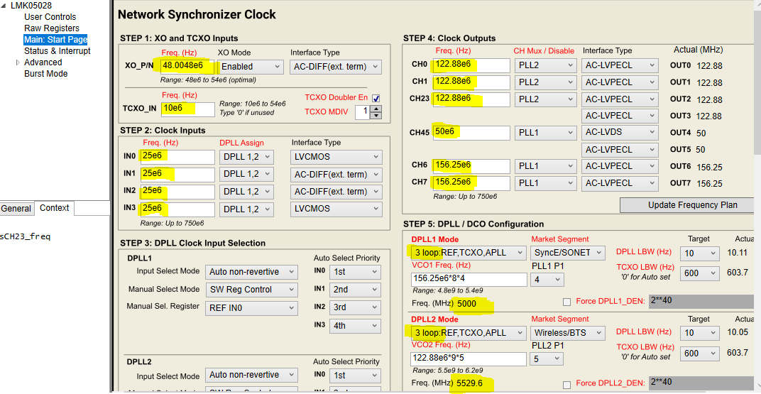
Using LMK05028EVM with default setting input frequency=25MHz LVCMOS, LOPL_DPLLX, LOFL_DPLL and HLDOVRX occur.

In order to resolve this failure,  what should we do at first time?


Kind regards,

Hirotaka Matsumoto

  • Hello, 

    First step should be to do a status readback and see whether the reference input is being validated or not. On the same status page that you observed the LOPL_DPLLx and LOFL_DPLLx, and HOLDOVERx, there is a REF box. In it it should check all references that are valid and it should let you know if either DPLL has selected a reference.

    Regards,

    Amin

  • Amin san

    Thank you so much for your cooperation.
    We checked all references that are valid.
    As the result, there is no valid clock input.
    Could you refer to the attachment file?
    20200228_LMK05028EVM.pdf

    It seems that input clocks are valid, however LMK05208 doesn't recognize these.
    And then, we attach .tcs file.
    20200228_LMK05028EVM.tcs

    About EVM setting, we use it with default setting.

    Kind regards,

    Hirotaka Matsumoto

  • Amin san

    We guess that your days are so busy, however if you have some update for our last post, could  you let us know?

    Kind regards,

    Hirotaka Matsumoto

  • Amin san

    Could you let us know your circumstance?

    Kind regards,

    Hirotaka Matsumoto

  • Hi Hirotaka san,

    The powerpoint attached saved us a couple of steps but it's also slightly confusing.

    What configuration were you using or were you trying to generate your own configuration? If you're trying to generate configuration, after updating the frequencies per your preference, you must run a runscript (circled red below).

    So for example just by updating IN0 to 1e6 Hz, it will not automatically result in DPLL registers changing to accommodate that input frequency.

    Secondly, the modes selected (highlighted below) are both "TCXO; APLL". In this mode the reference input is not being used at all. So REF DPLL will show LOPL, LOFL and HOLDOVER.

    So please clarify what configuration is being used.

    Thanks and regards, Amin

  • Amin san

    Thank you so much for your help!

    We operated "Run Script" with "3loop REF TCXO APLL," however, the result was the same.
    REF DPLL showed LOPL, LOFL and HOLDOVER yet.
    And then, we confirmed with input frequency = 25MHz, also the result was the same.

    Please refer to the following files;
    20200303_LMK05028EVM.pdf

    20200303_LMK05028EVM.tcs

    If you have some any advice, could you let us know?

    Kind regards,

    Hirotaka Matsumoto

  • Amin san

    If you have some update for our last update, could you let us know?

    Kind regards,

    Hirotaka Matsumoto

  • Hi Hirotaka san,

    The powerpoint has an image of the main start page, IN0 and IN3 are 1 MHz, in the .tcs file the frequencies of all inputs are 25 MHz, so which is the intended use? 

    There is also a lot of differences between the channel output frequencies and specifically VCO2 frequency in the 1 page attached in the powerpoint compared to .tcs file. If you confirm the highlighted numbers in the below image (which is from your .tcs file attached last) I can generate the config and test it on my bench to see if there are any issues. This process would be no different from just running a runscript. 

    Is the intention to use 3 loop mode? With a TXCO connected to TCXO input? So far your questions have only been about reference input, I just want to make sure TXCO input is being used, it's needed, and it's connected in your setup. 

    Lastly, the .tcs file status read back shows no references are valid. What is the signal source going into IN0? Do you know the swing level? pdf file shows 1 MHz clock with 1.8V swing... but seems like you're trying to use a 25 MHz clock so not sure if that's valid... We can disable some of the input validation features and see whether your signal is now being validated. This can be found on the main start page under reference input monitors, 2nd image below. 

    Regards, Amin

    Is what highlighted below correct and is this the intended configuration needed? I can runscript and confirm on my bench.. 

    Reference monitors - try disabling and re-enabling (which results in recalculation to confirm correct values) or just disabling to see if now reference is being validated: 

  • Amin san

    Thank you so much for your cooperation always!
    We finally could confirm valid Reference input by changing the register setting.

    Howeve, we could not get correct frequency output.
    Therefore, we confirm it now.
    If we have other questions, we will post the new forum.

    Kind regards,

    Hirotaka Matsumoto