This thread has been locked.

If you have a related question, please click the "Ask a related question" button in the top right corner. The newly created question will be automatically linked to this question.

CDCLVC1106: Driving a co-ax with a 50-ohm termination on load side, need more amplitude. Is it OK to parallel outputs to achieve this?

Part Number: CDCLVC1106

Hi.

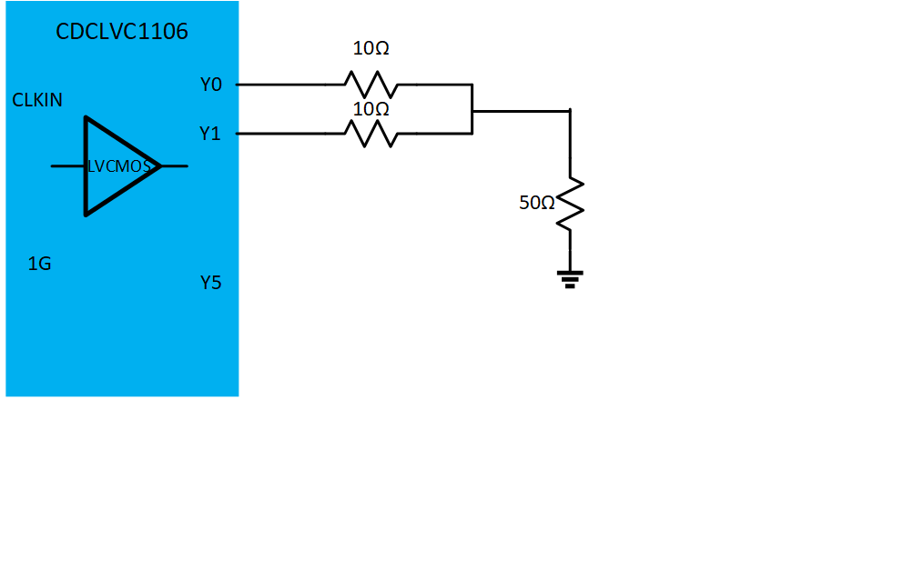
   I am using a CDCLVC1106 in an application where I need to distribute a precision 10MHz square wave clock to several pieces of lab equipment. On most of the equipment the receive side is 50-ohm terminated (as is good transmission line practice) and this 50 ohm termination is not removable.  When I use the CDCL1106 to send this signal it has insufficient drive current to give me the needed 3.3 volt swing to trigger the logic of some of the lab equipment. I found that if I tie the output of two channels of the '1106 together,  (each with a 10 ohm buffer resistor) I get enough drive to run the lab equipment. My question is, is this an OK thing to do?  Personally I see no difference of paralleling two output channels to that of having each channel drive its own load, but I am asking the experts. Will this affect the   pin-to-pin skew? Will this affect the jitter?  Better question may be, what part (if any) do you recommend for driving CMOS levels through transmission lines that are 50 ohm terminated?

  Thank you,

   ---Lou

  • Hi Lou,

    Please expect an update after the weekend. Thank you for your post.

  • Hi Lou,

                 I will be glad to help you with this query. As you must have observed, when you terminate a CMOS buffer with a 50 ohms resistance, the output will only swing to 0.5*VDD; this is the expected behavior as this is a essentially a voltage divider formed using the 50 ohm internal termination and the 50 ohm external termination. Generally it is not advised to terminate CMOS style drivers with 50 ohms since the driver may not be able to handle the huge currents (VDD/100 ohms = 33 mA in case of 3.3 V ) with such DC termination. 

    However in the case of your application, If i understand your solution correctly, you are trying to do something as shown in the figure below:

    This should be fine in terms of getting the drive strength you require, note that in the above figure, the output swing will essentially be VDD*(50/(50+50||50)) where 50||50 is the parallel resistance due to connecting two output channels in parallel. 

    Please note that, doing something like this will impact AC performance for the combined output. The reason for this is that there is a finite skew between any output channel and can be max of 50 ps as specified in the D/S. Therefore connecting the two outputs will impact jitter, rise-fall time etc. 

    You can get around this problem by two ways:

    1) AC coupling the output (You will only need one channel in this case) and DC biasing to the correct common-mode

    OR

    2) Using a device which has very low output resistance (higher output drive)

    Let me know if you need further clarification.

  • Yeah, the above is exactly what I did to get the output drive current I needed. Sort of a hack,

    but it works. 

    You said, 

    "2) Using a device which has very low output resistance (higher output drive)"

    Can you suggest a device that has a very low output resistance ? Is there a 

    line-driver made by Ti that you would recommednd?

      Thanks,

        ----Lou

  • Hi Lou,

               It will definitely work, but as i mentioned, performance will be compromised especially jitter. 

    I was able to do a quick search and did find a device which might be promising:https://www.ti.com/lit/ds/symlink/sn74lvt125.pdf?ts=1597731648386&ref_url=https%253A%252F%252Fwww.ti.com%252Flogic-circuit%252Fbuffer-driver%252Fnon-inverting-buffer-driver%252Fproducts.html

    Note that, i am not very familiar with the logic device family and would recommend to follow-up with someone from their apps team for clarification. Another thing to indicate is the logic device families are not necessarily optimized for jitter and they don't specify jitter in their datasheet. If your application is jitter and phase-noise critical, we can propose an alternate solution using the AC coupling cap and bias resistors.