This thread has been locked.

If you have a related question, please click the "Ask a related question" button in the top right corner. The newly created question will be automatically linked to this question.

LMC555: Voltage control range and response time

Part Number: LMC555

Dear Forum,

I am trying to use LMC555 as comparator ("zero" crossing detector) for triggering MSP430 ADC by interrupt.

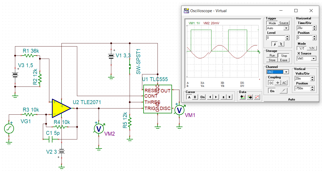
I would like to ask the VC (5) pin useful range guaranteed by design. For example my VDD is 3,3V, VC=1,5V. The signal is fed to TRIG pin (AC coupling, input is biased externally to comp level 0,75V).

If THR = L then '555 RS FF stores its last state (say, due to TRIG signal OUT->H, it Will store this H level despite further TRIG state). If THR=H, OUT can go back to L.

I experienced quite large (>300mVp) signal needed for reliable triggering and at higher frequencies could not trigged (n*10KHz) despite LMC is advertised a 3MHz device thus assuming it has

comparator response time in the 100ns range. Maybe both the VC both the VDD level is small.

Thanks,

Joseph

  • Hi Joseph,

    Can you provide a schematic so I can see exactly what you are working with. What is the input to your threshold pin?

    Best,

    Katlynne Jones

  • Hi Katlynne,

    My circuit:

    THR pin is controlled by a logic circuit (initially H) > when LMC Q goes to H (Trigged)  > Digital circuit pulls down THR to L (for certain time, I imitate this by a switch):

    It seems the TINA does take account to the real behaviour of the '555 analog circuitry (can handle for instance 10MHz / 20mV signal which is not realistic, of coarse). But I was suprised the real circuit could not handle some ten KHz / 100mV amplitude signal.

    Regards,

    Joseph

  • Hi Joseph,

    Thanks for sharing your schematic. 

    At a control voltage of 1.5V, the TRIG pin's "threshold" for it's internal comparator is 750mV. These trigger voltages from the datasheet can vary above or below the ideal value by at least 100mV. This is probably why you require this higher amplitude signals. 

    There's no guaranteed "useful" range of control voltages. The will all have some variance due to some mismatch between the internal resistors. If you are looking for high accuracy here then you may want to use a comparator with a more precise reference voltage. 

    The example in TINA is working because it is modeling the priority of the RS FF in a certain way. In the usual applications of the 555 timers, THR and TRIG are never held high, and low (respectively) at the same time. It looks like the model is giving priority to the TRIG input as well as not modeling the error in TRIG pin voltage as the datasheet shows. The high THR voltage is trying to pull the output low, and the low TRIG voltage is trying to pull the output high at the same time. I've seen that at lower control voltages, this polarity can flip. That could be a reason that you are having trouble triggering your timer (a high THR voltage is always pulling the output low). 

    You could try removing the control voltage and adding a 1.1V bias to the input instead to see if this helps, but I doubt it would reliably work with an input signal with an amplitude as low as 20mVp.  

    Another comment, if output is low when you pull THR low, the output will switch to high if TRIG goes low again in that time. Just want to make sure that you understand that it wont store that low state just because THR is low.

    Best,
    Katlynne Jones

  • Hi Katlynne,

    thanks very much for the obeservation!: the problem was caused (at low signal levels) by the tolerance of the on-chip resistor network as you remarked.

    I added a 500K trimmer resistor for fine adjustment of the Trigger level (VC pin removed from 1,5VREF and adding here the trimmer trap point) I made some oscillogramms (green waveform is the Q). Now it can trigger onto as small signals as 30mVp (tried with both square wave and sine) -> triggering is Q rising edge and HOLD this state by THRESHOLD=H (Digital circuit reacting to the trigger event).

    Yes, I understand, THR=L Will hold only the Q=H. If THR=H the Q can follow the trigger comparator (inverted) state.

    Kind regards,

    Joseph