This thread has been locked.

If you have a related question, please click the "Ask a related question" button in the top right corner. The newly created question will be automatically linked to this question.

LMK04906BEVAL: Status_LD / PLL2 DLD behavior.

Part Number: LMK04906BEVAL
Other Parts Discussed in Thread: LMK04906

I am evaluating the LMK04906 (using the TI eval board) for the purpose of generating 32.768MHz and 16.384MHz clocks which are sync'ed to the 8KHz timing reference generated by a TI TSB82AA2BI 1394b Link Layer Controller.

The LMK04906 single PLL/internal VCO setup is operational and the LMK04906 successfully locks the output clocks to the 8KHz reference and asserts the Status_LD / PLL2 DLD as long as the LLC is "Master" on the 1394 bus(very little jitter on the 8KHz reference).

However, if this particular PHY is a "Slave" on the 1394 bus (which creates up to 500ns cycle to cycle jitter in the 8KHz reference), the output clocks still achieve lock to the input but the Status_LD / PLL2 DLD output is unstable, changing between locked and unlocked. 

Are there any device settings which would stabilize the DLD operation with a jittered reference input ?

Danny

  • Hello Danny,

    The best method for stabilizing the DLD operation with a jittered reference input would be to switch from the single PLL setup to the dual PLL setup. In dual PLL mode, the first PLL (PLL1) can clean the jitter of the reference input and the second PLL (PLL2) will provide the output clocks.

    Here is the dual PLL mode functional block diagram and description:

    Another method is to set DISABLE_DLD1_DET = 1. If the unstable nature of the PLL DLD is causing a clock switch event, DISABLE_DLD1_DET can be set to 1 to prevent holdover mode from becoming activated due to the PLL1 DLD low transitions.

    Regards,

    Kia Rahbar

  • Kia,

    I started evaluations in the dual PLL mode since the eval board is configured for that.  I found that the PLL1 would lock to an un-jittered source, but would not lock to this same jittered source (PLL2/DLD2 locked to OSCIn from VXCO, but PLL1/DLD1 did not indicate lock and the the clock outputs were not synced to the reference input). 

    I then switched to single VCO mode and achieved the results in the original post.  Single VCO mode also provides a MUCH wider lock frequency range for the 8KHz input, due to the narrow adjustment range of the provided VCXO.

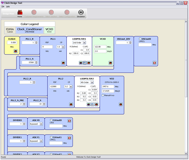
    I will add that in dual VCO I had some difficulty using the loop filter values for an 8KHz reference as calculated by the TI Clock Design Tool, they did not work at all. So testing was done by adding capacitance to the provided C2_VCXO until it worked down to 8KHz, probably not optimal. If you can provide recommended values for C1_VCXO, C2_VCXO, and R2_VCXO, I will be happy to retest dual PLL mode.

    But back to the original question:  so there are no setting/options that affect the behavior of the DLD2 signal? (since the PLL2 is actually locked, just the status indication is unstable)

    Thanks Again,

    Danny

  • Hello Danny,

    Here are the values I would recommend for C1_VCXO, C2_VCXO, and R2_VCXO given your configuration:

    The answer to your original question would be to follow method 2 above. The DISABLE_DLD1_DET can be enabled (set to 1) to prevent the flickering of the PLL DLD. This method disables the PLL DLD pin, therefore you must manual verify the PLL locks. This method results in you ignoring the PLL DLD lock indication. If you are certain your PLL is locked then this method would work for you.

    Regards,

    Kia Rahbar

  • Kia,

    The VCXO provided on the Eval board is 122.88MHz, which I believe is why the Clock Design tool gave me slightly different values:

    but I will give these values a try and report back.

    Thanks,

    Danny

  • Kia,

    I retested with your values for C1, R2, and C2 and again found that PLL1 would not lock to a stable 8KHz input reference.  I experimented with the input reference frequency and found these results:

    64KHz input – PLL Locked, DLD1  Status Good

    32KHz input – PLL Locked, DLD1  Status Bad

    16KHz input – PLL Locked, DLD1  Status Bad

    8KHz input – PLL NOT Locked, DLD1  Status Bad

    Any other ideas?

    Thanks

  • Hello Danny,

    The only other method would be to enable the DISABLE_DLD1_DET (set to 1) to prevent the flickering of the PLL DLD. This method disables the PLL DLD pin, therefore you must manual verify the PLL locks. This method results in you ignoring the PLL DLD status indication. If you are certain your PLL is locked then this method would stabilize the DLD. 

    Regards,

    Kia Rahbar

  • Sorry Kia, I wasn't clear.

    I meant any other ideas why PLL1/External VXCO will not lock to an 8KHz reference on the eval board?  It's definitely frequency related as the system works very well down to about 64KHz.

    Operating without a functional Lock status indicator is not an option in our system.

    Thank You

  • Hello Danny,

    Try following the steps discussed in the following post: https://e2e.ti.com/support/clock-and-timing/f/48/p/440961/1587104?tisearch=e2e-sitesearch&keymatch=lmk04906%252520unlocked#1587104. Specifically look at the last post in the thread.

    Regards,

    Kia Rahbar