This thread has been locked.

If you have a related question, please click the "Ask a related question" button in the top right corner. The newly created question will be automatically linked to this question.

LMK03318: Behavior is different between programming registers over I2C and reading the same values from EEPROM

Part Number: LMK03318
Other Parts Discussed in Thread: , USB2ANY

I am planning to use the LMK03318 on a two channel 160 MSPS ADC data capture board and I’d like to program the clock settings using the built-in LMK03318 EEPROM.

I used the TICS Pro utility to enter my clock configuration (160 MHz balanced on Output 0 and 25 MHz single end on Output 7) and exported the register settings to a file.  I then used a home grown fixture with I2C to program these register values into the LMK03318 (I’m using the LMK03318EVM configured for an external I2C connection).  I’m pretty confident that the fixture I2C communication is working because I can access Read only registers and find their correct values, and program R/W registers and read back the correct changed value.

When I boot the LMK03318EVM with HW_SW_CTRL=1 and GPIO0-5=0, I get a clean clock on Output 0, per the settings of ROM page 0.  If I then use my fixture to program my saved register settings, I get a clean 160 MHz clock on Output 0. So far so good.  However the 25 MHz clock that is supposed to be on OUTPUT7 is instead 83.33 MHz

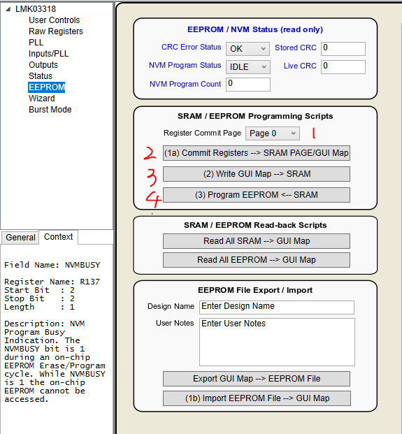
Next, if I then use the programming steps to save those register settings to EPROM page 0 and then power cycle with HW_SW_CTRL=0 GPIO0-5=0, I don’t get a clean clock on Output 0.  Instead it seems noisy and variable.  As far as I can tell, the right register values have been read back from the EEPROM page.  In this state I have tried toggling both PDN and R12.7, neither of which many any difference.

Does the order in which the registers are programmed via I2C make a difference in this scenario?  I have attached the saved register file.

To summarize I have two problems.  1) In the “working” case the 25MHz output is wrong and 2) nothing works when the apparently correct register values are read back from EEPROM.

HexRegisterValues_lmk33018_160.txt
R0	0x0010
R1	0x010B
R2	0x0233
R3	0x0301
R4	0x0400
R5	0x0500
R6	0x0600
R7	0x0700
R8	0x0800
R9	0x0900
R10	0x0AA0
R11	0x0B00
R12	0x0CD9
R13	0x0D00
R14	0x0E1D
R15	0x0F00
R16	0x1000
R17	0x1100
R18	0x1200
R19	0x1300
R20	0x1455
R21	0x1555
R22	0x16FF
R23	0x1703
R24	0x1800
R25	0x1955
R26	0x1A00
R27	0x1B58
R28	0x1C28
R29	0x1D06
R30	0x1E1E
R31	0x1F20
R32	0x2000
R33	0x210E
R34	0x2200
R35	0x2300
R36	0x2403
R37	0x2500
R38	0x2602
R39	0x2700
R40	0x2802
R41	0x2900
R42	0x2A05
R43	0x2B3E
R44	0x2C5F
R45	0x2D0A
R46	0x2E00
R47	0x2F00
R49	0x3100
R50	0x3297
R51	0x3303
R52	0x3400
R53	0x3500
R54	0x3600
R55	0x3700
R56	0x3806
R57	0x3918
R58	0x3A00
R59	0x3B30
R60	0x3C00
R61	0x3D00
R62	0x3E00
R63	0x3F00
R64	0x4000
R65	0x4101
R66	0x420C
R67	0x4304
R68	0x4401
R69	0x4504
R70	0x4607
R71	0x471F
R72	0x4818
R73	0x4900
R74	0x4A64
R75	0x4B00
R76	0x4C00
R77	0x4D00
R78	0x4E00
R79	0x4F00
R80	0x5001
R81	0x510C
R82	0x5224
R83	0x5300
R84	0x5400
R85	0x5500
R86	0x5600
R87	0x5700
R88	0x5800
R89	0x59DE
R90	0x5A01
R91	0x5B18
R92	0x5C01
R93	0x5D4B
R94	0x5E01
R95	0x5F86
R96	0x6001
R97	0x61BE
R98	0x6201
R99	0x63FE
R100	0x6402
R101	0x6547
R102	0x6602
R103	0x679E
R104	0x6800
R105	0x6900
R106	0x6A05
R107	0x6B0F
R108	0x6C0F
R109	0x6D0F
R110	0x6E0F
R115	0x7308
R116	0x7419
R117	0x7500
R118	0x7607
R119	0x7701
R120	0x7800
R121	0x790F
R122	0x7A0F
R123	0x7B0F
R124	0x7C0F
R129	0x8108
R130	0x8219
R131	0x8300
R132	0x8403
R133	0x8501
R134	0x8600
R135	0x8700
R136	0x8800
R137	0x8910
R138	0x8A00
R139	0x8B00
R140	0x8C00
R141	0x8D00
R142	0x8E00
R143	0x8F00
R144	0x9000
R145	0x9100
R169	0xA940
R172	0xAC24
R173	0xAD00

  • Hi Eric,

    Can you send over the .tcs file instead? You can do File -> Save. Zip it if you can't upload a .tcs file.

    Regards,
    Hao

  • Hi Eric,

    For the first question, the configuration looks correct to me. Can you check if manually changing the OUT7 divider will make the output frequency 160MHz?

    Follow below steps to write the register content to EEPROM page 0:

    Regards,
    Hao

  • As your first point, I tried manually changing R44 from 96 to 15 but it made no apparent difference.  The output on OUT7_N and OUT7_P is still noisy and variable.  OUT_0 is still 160 MHz.

    You comment about programming the EEPROM appears to refer to the case where the App is communicating with the target device over USB.  I don't have that case (I have the hardware, but I couldn't get it to work).  Instead I have my own fixture that communicates over I2C with the LMK03318.  As I said above, I have been successful at getting the modified register settings saved to EEPROM -- it just doesn't work when they are read back.

  • Hi Eric,

    First of all, check if the PLL is locked. To do so, measure the voltage on pin STAT1. In the configuration that you sent, STAT1 is active high, meaning that if the voltage is 3.3V, then "LOL" status is active. LOL stands for Loss of Lock. Therefore, high means not locked and low means locked.

    If the PLL is locked, check if other outputs can successfully generate a clock. Since there's only one PLL, all the outputs share the same source. If one output cannot generate a clock, then the problem is with that output.

    Try disabling the output synchronization and see if that helps:

    Regarding the EEPROM programming, to verify whether or not the EEPROM is successfully written, it's recommended to use the "direct access" method. You can generate a EEPROM image from Ticspro by clicking this button:

    You can also directly read the EEPROM image back from a chip. If you don't have access to a USB2ANY, you can try implementing that yourself according to the datasheet. The goal is to compare the two EEPROM images (written and read). The first 10 bytes are protected so it's OK that they're different. The rest bytes should be exactly the same.

    The reason why this is needed is because not all registers are stored in the EEPROM. There're read only registers and some other registers that don't need to be stored. Therefore if you read back registers you may get different values.

    Regards,
    Hao

  • Progress!

    First of all, yes I have checked PLL lock by looking at STAT1 and it has always been good, meaning Loss of Lock if Off.

    Your suggestion of turning off PLL_SYNC has improved things.  Now, when I boot with HW_SW_CTRL=0 and read back the latest settings from the EEPROM, I now get a good 160 MHz on OUT0.  PLL Loss of Lock is Off.  However, I have never achieved a good clock on OUT7, whether I just write the registers over I2C or cause them to be read from EEPROM.

    So one of two problems addressed.

  • Hi Eric,

    That might be because of the prescaler setting. In general, the prescaler shouldn't be set to 2 if output sync is ever needed (which is mentioned in the datasheet). So you can either keep the sync off or select another solution with prescaler not equal to 2.

    Regarding OUT7, can you start from the EVM default configuration (in Ticspro tool bar -> default configurations) and see if the default config works? just in case you accidentally edited some register. If the default config works, then go step by step and see where OUT7 is gone.

    Regards,
    Hao