This thread has been locked.

If you have a related question, please click the "Ask a related question" button in the top right corner. The newly created question will be automatically linked to this question.

LMX2572EVM: LMX2572EVM connection and Refernce Pro circuit diagram, pattern diagram

Part Number: LMX2572EVM
Other Parts Discussed in Thread: USB2ANY

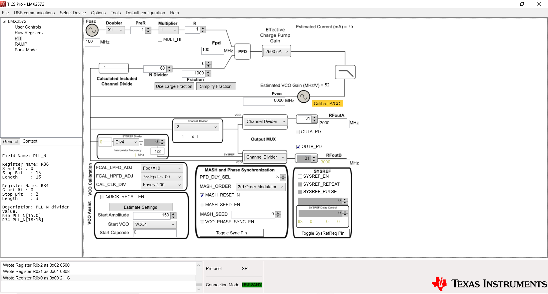
I have purchased the LMX2572EVM and evaluated it, but when I run it with TCS Pro in Default Configuration, it should lock in the 3GHz band, but it oscillates without locking in the 2.7GHz band.

"User's Guide SNAU217B–August 2017–Revised July 2019 LMX2572EVM Evaluation Instructions "

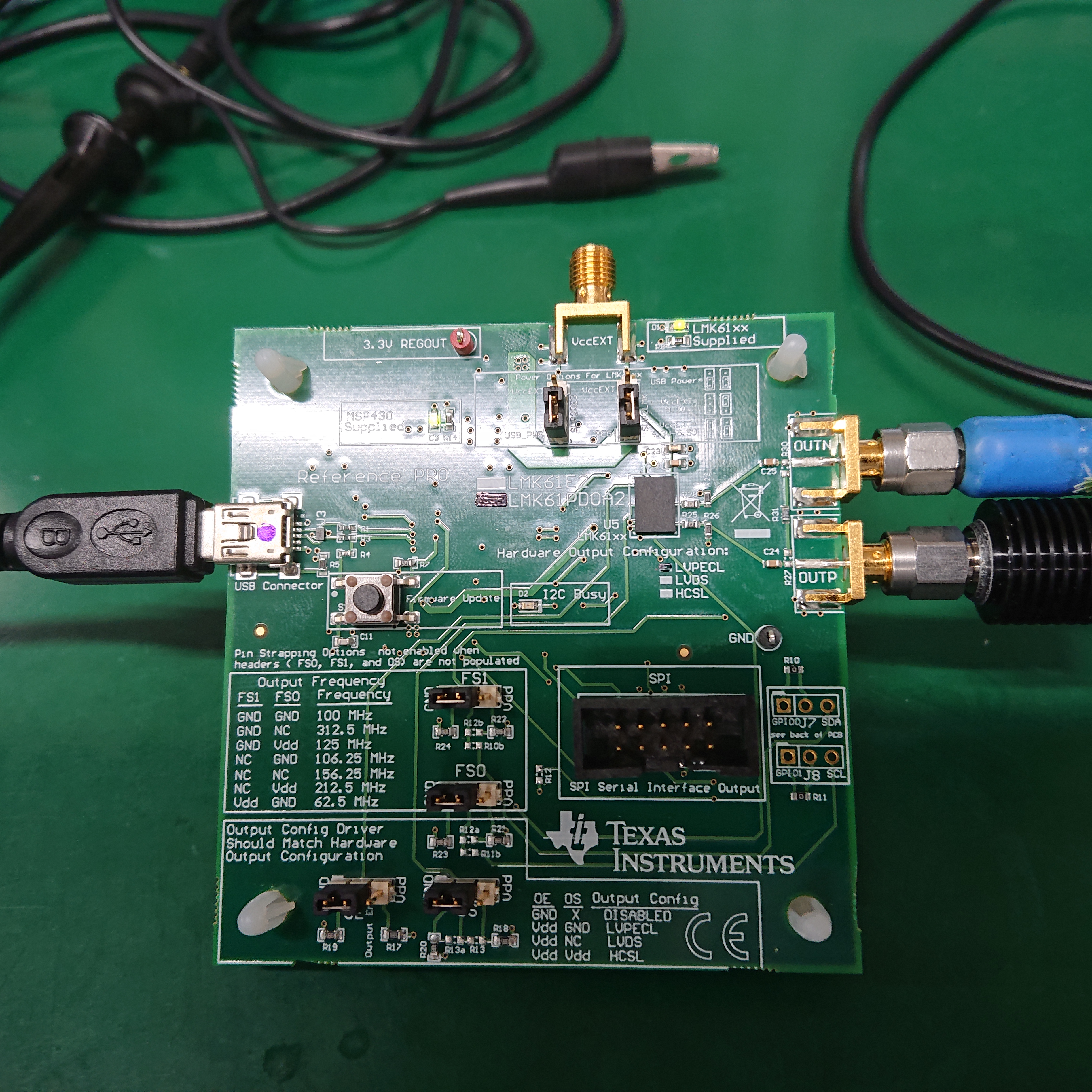
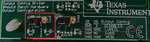
Comparing the connection diagram on p.3 and the case of connecting according to the connector shape of the cable attached to the LMX2572EVM that we purchased,

the position of the red line is opposite on the LMX2572EVM side as shown in the attached figure (in the figure). (Upper right), is this correct?

I searched for the pattern diagram and circuit diagram on the Refernce Pro side to check. I couldn't find it. Could you please provide it together?

EVM.pdfThank you.

  • Hi there,

    The red line of the ribbon wire in the EVM setup diagram was not drawn "in scale", its position is not matter. To check if you can communicate with the EVM, power down the EVM by writing POWERDOWN = 1, if you see current drop, that means there is no issue in programming the EVM. 

    Regrading the unlock issue, make sure you have selected the "Default mode" and pressed Ctrl + L keys to load all the registers once. If it is unlocked, click the CalibrateVCO button (next to the VCO), which will program R0 once and calibrate the VCO. By the way, check that the Reference Pro board as a 100MHz clock output. 

  • thank you for your answer.

    I checked

    1)"power down the EVM by writing POWERDOWN = 1, if you see current drop, that means there is no issue in programming the EVM. "
    →OK

    2)"make sure you have selected the "Default mode" and pressed Ctrl + L keys to load all the registers once.
    If it is unlocked, click the CalibrateVCO button (next to the VCO), which will program R0 once and calibrate the VCO."
    →All the registers seem to be flowing. I pressed the VCO Cal but it doesn't seem to lock.


    3)"By the way, check that the Reference Pro board as a 100MHz clock output."
    →It seems that 100MHz output is not output.
    The board status of Reference Pro and the setting face of TICS Pro are attached.

  • As for additional information, it worked when I input it at 100MHz with USB2ANY and an external SG.

  • Hi there,

    The Reference Pro header setting is not correct. OE should be strapped to Vdd, right now you have the 100MHz output disabled.

  • I was able to confirm that 100MHz was output and the lock was set. Thank you very much.