This thread has been locked.

If you have a related question, please click the "Ask a related question" button in the top right corner. The newly created question will be automatically linked to this question.

LMK03806: lmk03806 PLL divider values

Part Number: LMK03806
Other Parts Discussed in Thread: PLLATINUMSIM-SW, LMK03318

Hi,

I am using LMK03806 in my design. Design details are as below

FOSCin = 10 MHz

Output frequency to be generated = 204 MHz

I am planning to go with Fvco = 2448 MHz. 

Kindly suggest the PLL divider values for the best performance.

Also, elucidate the impact of Phase detector frequency in the overall jitter performance.

Thanks in advance,

Pratiksha

  • Hello Pratiksha,

    The LMK03806 includes a doubler, so the highest available reference frequency is 20MHz. the VCO frequency must be 2448MHz, because no other valid divides can make 204MHz. GCD(2448, 20) = 4MHz, so you would enable the reference doubler, set the R-divider to 5, and set the total N-divide equal to 612. Valid prescaler/N-divider combinations include:

    • 2 & 306
    • 3 & 204
    • 4 & 153
    • 6 & 102

    There is no great benefit for one value over another, but usually we recommend the highest prescaler value to reduce the total number of N-divider stages used.

    In general, the higher the phase detector frequency can be made, the in-band noise will be lower and the PLL bandwidth will be higher. Please note that we have a model for the LMK03806 in PLLatinum Sim (PLLATINUMSIM-SW), which can be used to model the impact of different phase detector frequencies, charge pump gains, loop filter bandwidths, etc.

    Regards,

    Derek Payne

  • Hi Derek,

    For some reasons,  I am not able to download the software PLLatinum Sim.

    Kindly, check the clock jitter performamce for my design requirements.

    Since, Phase detector frequency of 4 MHz seems to be very less to get proper jitter performance. 

    Thanks in advance,

    Pratiksha

  • Pratiksha,

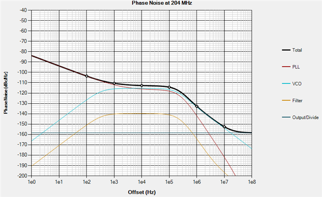
    I agree, the 4MHz loop filter is definitely preventing you from achieving better RMS jitter numbers than I would otherwise expect. I get around 1200fs RMS 12k-20M @ 204MHz carrier, with C1=10pF, C2=56nF, R2=8.2kΩ, and integrated components set to C3=18pF, C4=10pF, R3=680Ω, R4=200Ω. The PLL noise is the majority contribution, due to the low phase detector frequency. I don't think you can optimize much beyond this, as you are encountering a fundamental limitation due to your device choice and reference/output frequency requirements.

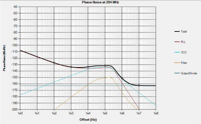
    I think you may be better off using something cost-comparable like LMK03318 instead, with a higher VCO frequency that supports 20MHz phase detector and a higher current charge pump to help push down PLL noise contribution. Without much optimization, 5100MHz VCO, N-divider=255, 20MHz phase detector, 6.4mA charge pump gain, output divider of 25, I get around 175fs RMS 12k-20M @ 204MHz carrier. C1 = 450pF, C2=4.7nF, R2=~1.2kΩ, C3=10pF, R3=18Ω.

    Regards,

    Derek Payne