This thread has been locked.

If you have a related question, please click the "Ask a related question" button in the top right corner. The newly created question will be automatically linked to this question.

LMX25311570EVAL: The LC tank structure and the VCO calibration of LMX2531

Part Number: LMX25311570EVAL

Hi all,

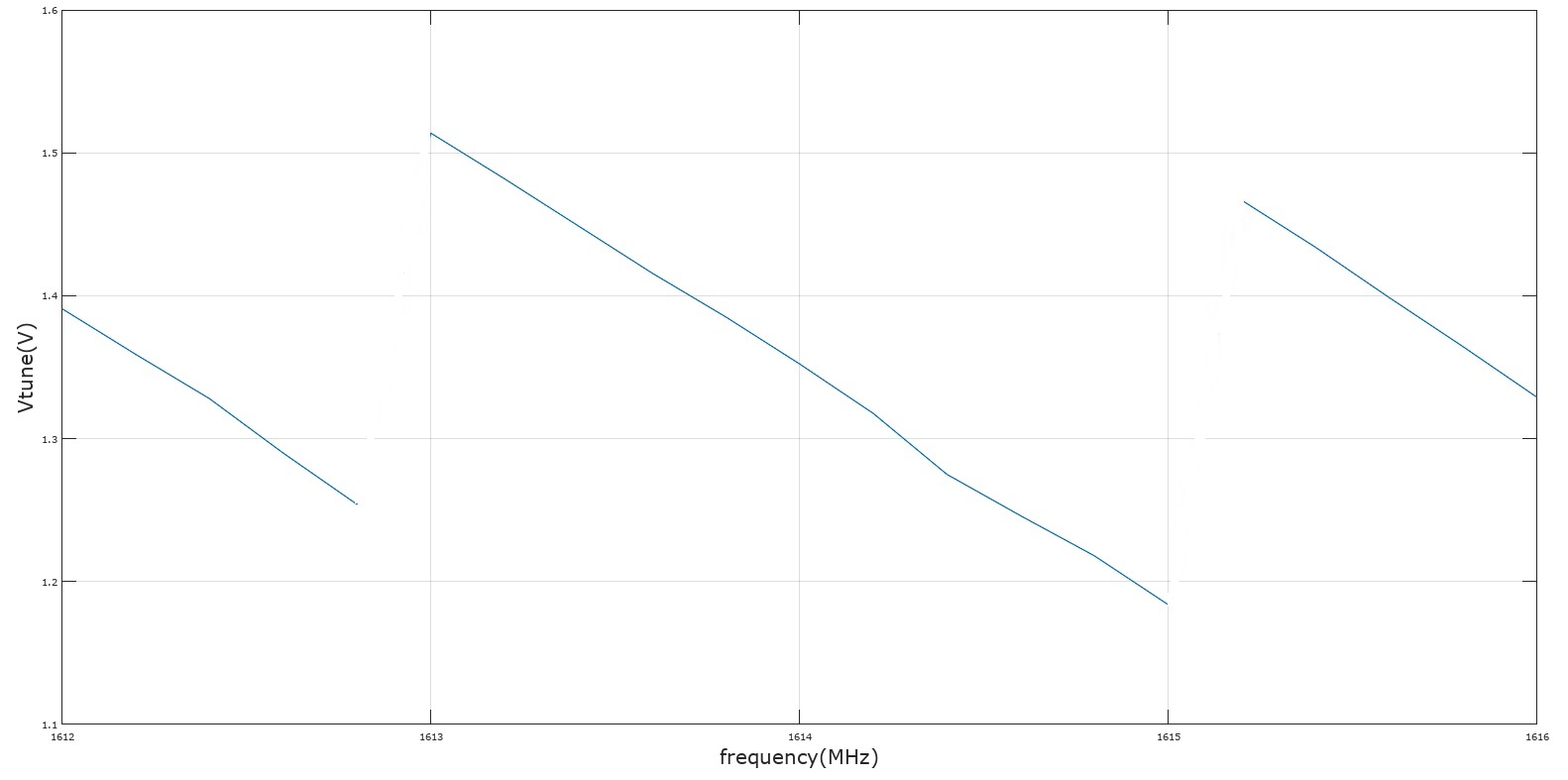
Recently, I measured the Vtune pin to find the locked time.

To the best of my knowledge, the switching capacitor is used in the LC tank structure.

My first question is, can anyone give me the frequency of each sub-band?

And what is the type of the variable capacitor? varactor diode or MOScap?

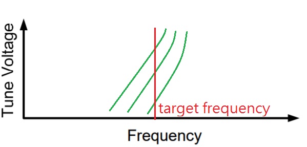
My second question is that, according to "PLL Performance, Simulation, and Design 5th Edition" written by Dean Banerjee, the Vtune is fixed during VCO calibration.(searching the optimal capacitor combination)

However, in my Vtune measurement (please see the following picture), the voltage actually jump to a higher value before tracking to the target frequecny.

What is the reason of that voltage changing?

  • Hello Sam,
    our experts will come back to you!

    Best regards,
    Patrick
  • Sam,

    The LMX2531 uses a single inductor (formed by package bond wires) and has 128 different frequency bands formed by the 128 possible capacitor values. We don't guarantee the frequency range of any sub-band and there is considerable overlap to allow for drift over temperature. The "Kbit" number in the datasheet is how much the frequency changes if you change one band (2.1 Mhz for the LMX2531LQ1570E). I think that the band is probably closer to 5-10 MHz wide as there is overlap.

    The same varactor diode capacitance is used for each sub-band and there are fixed capacitors switched in.

    In your picture, you are seeing the device fix the tuning voltage at 1.5 V during the VCO calibration process, which involves switching between the capacitors and also optimizing the amplitude. I'm not so sure about the red box area where it becomes higher, but there is more than one frequency and amplitude calibration and also I think that the 1.5V is internally applied to the VCO and this 1.5V might not be connected to the loop filter during the entire VCO calibration process.

    Regards,
    Dean
  • Hi Dean,

    Thanks for the reply.

    The voltage in the red box still confusing me because I thought after finding the optimal capacitor combination, the VCO should start to track the target frequency right away.

    So you mean that, the PLL might rise the voltage and do another VCO calibration even if the last calibration process have already found the correct sub-band?

    Best regard,

    Sam

  • Hi Dean,

    I found that you mentioned in your book that the optimal capacitor combination is the combination that "best centers the VCO frequency".

    Is that the reason which the VCO need more than one calibration procedure? Because the sub-bands overlap with each other, one calibration procedure is not enough to decide the optimal one. So the Vtune is rised to do another VCO calibration.

    For example, in the following picture, the target frequency is the red line. Which sub-band will be chosen after VCO calibration? The middle one?

    Best regards,

    Sam

  • Dean,
    I also want to know that when performing VCO calibration, what is the frequency comparator in the procedure? PFD of the PLL or another digital comparator?

    Thank you,
    Sam
  • Sam,

    The state machine clock frequency used for the digital calibration has a frequency of Fosc/XTLDIV

    Fosc is the input frequency

    XTLDIV is a programmable word in the LMX2531 which can be 1,2,4, or 8

    Regards,

    Dean

  • Dean,

    So the phase frequency detector compare the Fosc/XTLDIV and the VCO frequency?

    Or there is another circuit to compare these two frequencies and control the capacitor bank?

    Best regards,

    Sam

  • No, Fosc/PLL_R is compared to Fvco/PLL_N.
    However, there is a state machine that determines how often this comparison done, and this is Fosc/XTLDIV.
    This state machine clock also drives the amplitude calibration.

    Regards,
    Dean
  • Dean,

    Thanks for the reply!
    Back to my previous question, you mentioned that "there is more than one frequency and amplitude calibration".
    Why the extra calibration is needed if the first calibration have already found the optimal capacitor combination?

    Best regards,
    Sam
  • Sam,
    The frequency and amplitude calibration settings are interdependent variables and the impact each other.

    So suppose it does something like this:
    1. Force amplitude setting to 5
    2. Find the optimal frequency band to 93
    3. Based on frequency band of 93, optimize the amplitude calibration setting. Say now it decides that 9 is optimal for phase noise
    4. But then now the frequency bands are shifted, so frequency band 93 is no longer optimal. So do frequency calibration based on assuming amplitude setting is 9.
    5. Suppose frequency calibration now decides that band 91 is optimal
    6. But now since the band has changed, amplitude setting of 9 might not be optimal for band 91 (it was optimal for band 93). So re-run amplitude calibration. Say it comes back at 8
    7. So finish calibration with frequency band of 91 and amplitude setting of 8.

    Regards,
    Dean
  • Dean,
    Is the amplitude calibration equivalent to phase noise calibration?
    Can you explain how the amplitude calibration work?

    Thank you,
    Sam
  • Dean,
    Sorry that my last question seems to be ambiguous.
    Just want to know when the amplitude setting is changed, which part of the LMX2531 will be influenced?
    Does the word "amplitude calibration" mean that finding the optimal Q factor?

    Thank you for answering these basic questions,
    Sam
  • Sam,

    There are two things needed to tune for the VCO, for purposes of discussion:
    1. VCO_CAPCTRL, also called "frequency band"
    This is an internal capacitor setting. Realize that the VCO tank also has some fixed capacitance. A value of 0 means no internal caps switched and the VCO is highest frequency band. A value of 128 is the highest setting and means all the caps are switched in and lowest setting.

    The term "frequency calibration" refers to the process of trying different values of VCO_CAPCTRL to find the one that gets the VCO closest in frequency for a tuning voltage of 1.5V. Also realize that this is only valid for a specific value of VCO_DACISET and VCO_DACISET has a small impact on frequency. So the idea is you fix VCO_DACISET, hoping it is close to the final value, then sweep VCO_CAPCTRL.

    2. VCO_DACISET, also called "amplitude setting"
    ThisT refers to an internal tank voltage of the VCO. To a point, higher is better, but if it is too high, then there is saturation and phase noise degrades. Therefore an "amplitude calibration" is used to find the optimal amplitude that gives the best phase noise (right before tank amplitude starts to saturate). "Q factor" is really more about the inductor. Realize that although VCO_DACISET has the largest impact on phase noise, it does change with VCO_CAPCTRL. So the amplitude calibration has to be done for a specific value of VCO_CAPCTRL.


    So as the optimal values of VCO_CAPCTRL and VCO_DACISET are interdependent, this is why we run the calibration more than once.

    Regards
    Dean
  • Dean,

    So the "amplitude calibration" is the procedure to find the optimal output voltage of VCO to optimize the phase noise?

    In your previous reply, you mentioned that :
    "3. Based on frequency band of 93, optimize the amplitude calibration setting. Say now it decides that 9 is optimal for phase noise
    4. But then now the frequency bands are shifted, so frequency band 93 is no longer optimal. So do frequency calibration based on assuming amplitude setting is 9."

    Does this mean that, when you change the amplitude setting, the frequency band might become different to find the lowest phase noise.
    For example, when amplitude is set to 9, frequency band 93 is no longer optimal for phase noise, so the extra frequency calibration is needed to optimize phase noise?

    Best regards,
    Sam
  • Yes, this why it runs the calibration more than once.

  • Dean,

    One more question, what is the maximum value and minimum value of Vtune? 

    Thank you,

    Sam

  • 0 to 2.5 V, but preferably stay away from the rails (i.e 0.5 to 2 V for good performance)

  • Dean,

    I measured the Vtune of several frequencies and found that when the frequency become higher while Vtune is reduced.(shown in the following picture)

    What is the reason of this result?

    Thank you,

    Sam

  • Sam,

    This VCO has a negative tuning coefficient.

    By the way, can you tell me about what end product this is for?

    Regards,
    Dean
  • Dean,

    To the best of my knowledge, typical Kvco is positive because the capacitance of varactor diode is reduced as I increase the Vtune which will increase the oscillation frequency.

    What is the reason of the negative Kvco?  


    By the way, the synthesizer will be using in production testing equipment and will not use in the product.

    Thank you,

    Sam

  • Sam,

    I don't know the reason for the negative Kvco, but all products have this, so I am sure that there is a compelling reason. It might have something to do with special properties of our capacitors integrated on silicon and this driving the architecture of the VCO, but I am just speculating. Although I could pursue this to get complete answer, some of the aspects of our integrated VCO are considered intellectual property by our design team. So let's just leave this as it's due to the architecture.

    Regards,
    Dean