This thread has been locked.

If you have a related question, please click the "Ask a related question" button in the top right corner. The newly created question will be automatically linked to this question.

ADS1118: DOUT high all the time

Part Number: ADS1118
Other Parts Discussed in Thread: MSP430F5529

Hello,

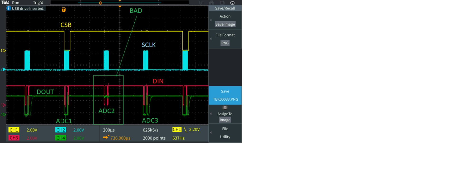
I'm connecting 3 magnetometers to 3 ADS1118s. Two of the ADS1118s are functioning OK, but one ADS1118 has a high DOUT all the time (see attached scope shot). 

I've tried debugging with the following:

  • Measured the input to the bad ADS1118, and the differential input ~10mV (the ADS1118's FSR is 1.024V)
  • Made sure the bad ADS1118's DOUT is not connected to VDD because all the ADS1118's DOUT are tied together, and DOUT for the other two ADS1118 are OK
  • I even tried disabling the internal ADS1118 pull-up but that didn't help
  • I made sure the CSB for the bad ADS1118 is toggling at the right time and only when I'm calling that ADS1118
  • I have 20 boards like this, and I'm seeing this problem on 2 boards; the other 18 boards all have working ADS1118s

Is there anything else I can try to troubleshoot this issue? My last resort is to swap out the bad ADS1118 but it's quite hard since it's only a flex board and doing so might damage the board.

Thanks. 

  • Amy,


    Your scope shot didn't get attached to your post, so when you post back, attach the picture again.

    Just to be sure, you have 18 boards that work, and 2 boards that exhibit this problem? If that's the case, I'd guess that the issue comes from the board assembly.

    However, I wouldn't just check for a short between DOUT and VDD. If /CS is shorted high or not connected, then the chip would never respond to anything. Also, if the SCLK were disconnected, the response would be the same (although I would have guessed the default of the device to start low).

    If you have a chance respond by posting the scope shot, just in case there's something to check in the response. It might also help to have a layout of the board with a schematic, just in case. Are you using the RUG or DGS version of the package?


    Joseph Wu
  • Hi Joseph,

    Thanks for the reminder. I'm attaching the picture here.  I am scoping all three ADS1118s but I'm only showing the CSB for the first ADC.  As you can see, the second ADC is pulled HIGH all the time.  

    Also note that I tried communicating to this board using two separate systems (OpalKelly FPGA and MSP430F5529), and both are seeing the same result. And yes, I only see issues for 2 out of the 20 boards. 

    I'm using the DGS package.  Unfortunately, I can't share the layout as it is proprietary.  I do have other sensors on this board, but when I was scoping the SPI signals, the master was only communicating to just the 3 ADS1118 on board. 

    What else can I probe to figure out why this issue is occurring? 

    1. I already verified dVIN of 10mV is within the FSR of 1.024V. Should I try playing around with the FSR to see if that makes a difference? 
    2. I haven't probed VDD yet so I can make sure it's 2V
    3. I can also try to capture the scope screen shots while probing on the bad ADS1118's SPI pins. Probing is quite hard as these ADCs are on a flex board so we have to use a probing machine for this.
    4. As mentioned, my last resort is to swap the ADS1118

    Thanks


  • Amy,


    Looking at the scope, it does look like there's some small movement on the DOUT line but that's very revealing.

    Normally, I might try to reflow the device on the board to see if there is a bad connection. Unfortunately, there aren't a lot of good or easy options to check the device. Almost everything requires the DOUT line to show that there's something happening with the device. At this point, it looks like DOUT might be stuck to VDD through a low impedance.

    I might try looking at the supply current if you have a series supply resistor. Or if you have a series input resistor, you could set the device to the smallest input range and see if you can measure the input current, to match the equivalent analog input impedance (differential) in the datasheet. If the input current is correct, it shows that the ADC is working and sampling the input.

    I might also visually inspect the boards to see if there's a bad connection elsewhere. I'd look at all the digital line traces from the ADC all the way back to the microcontoller (Incidentally, are all the DOUTs connected together? Or do they go to separate pins of the microcontroller? If they are separate pins, is the pin properly programmed as an input? If they are together, then there can't be a short to VDD or all devices would be stuck).

    Short of pulling up the device and replacing it with a new one, that's all I can think to recommend at this point.


    Joseph Wu
  • Thanks, Joseph. I will consider measuring the ADC's supply current.

    By the way, if we are not using AIN2 & AIN3, do we need to GND them or we can leave them floating? 

  • Amy,

    The recommendation that TI has for unused pins is to leave them floating or tie them to VDD. We mention that in the pin functions table of the datasheet.

    Joseph Wu