This thread has been locked.

If you have a related question, please click the "Ask a related question" button in the top right corner. The newly created question will be automatically linked to this question.

ADS7953: SPI not working manual mode

Part Number: ADS7953


Dear Sir/Madam,

I have used ADS7953 ADC to read 16CH input of voltage range 0V to 5V.  VA+ = 5V, VBD = 3.3V , REFP = 2.5V  and REFM = 0V (GND). 

On board I have constant voltage source generating 4.096V (U10 in schematic) and connected to CH11 input of ADC. The host controller is RPI model 3B+.

The problem is on configuring the ADC to manual mode, I have to read CH11 to get 4.096V. But here I get 0 value on MISO line ( it is in tri-state even after pull up to 3.3V using 4.7KE). 

Schematic - 

ADS7953_Sch.pdf

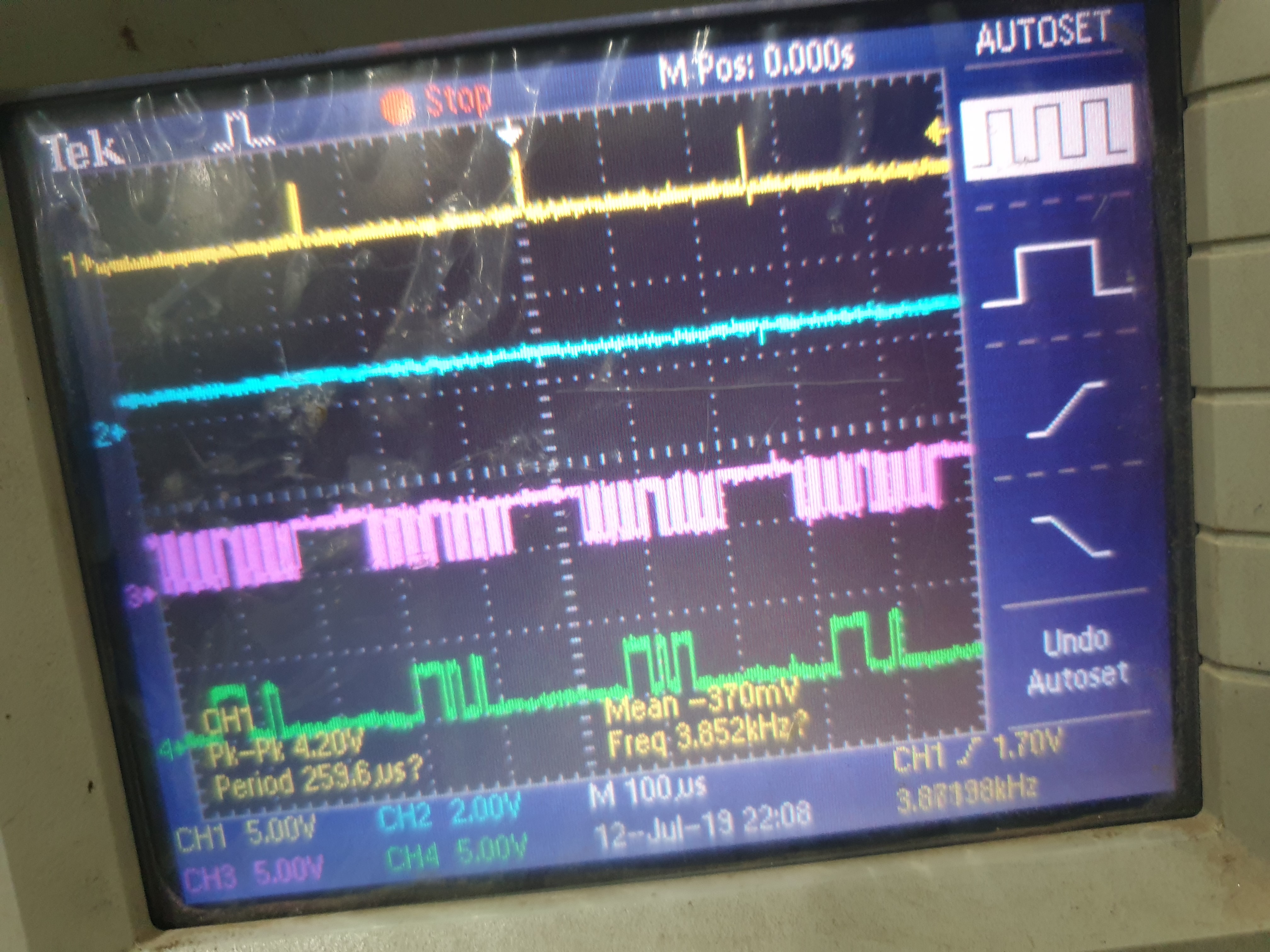
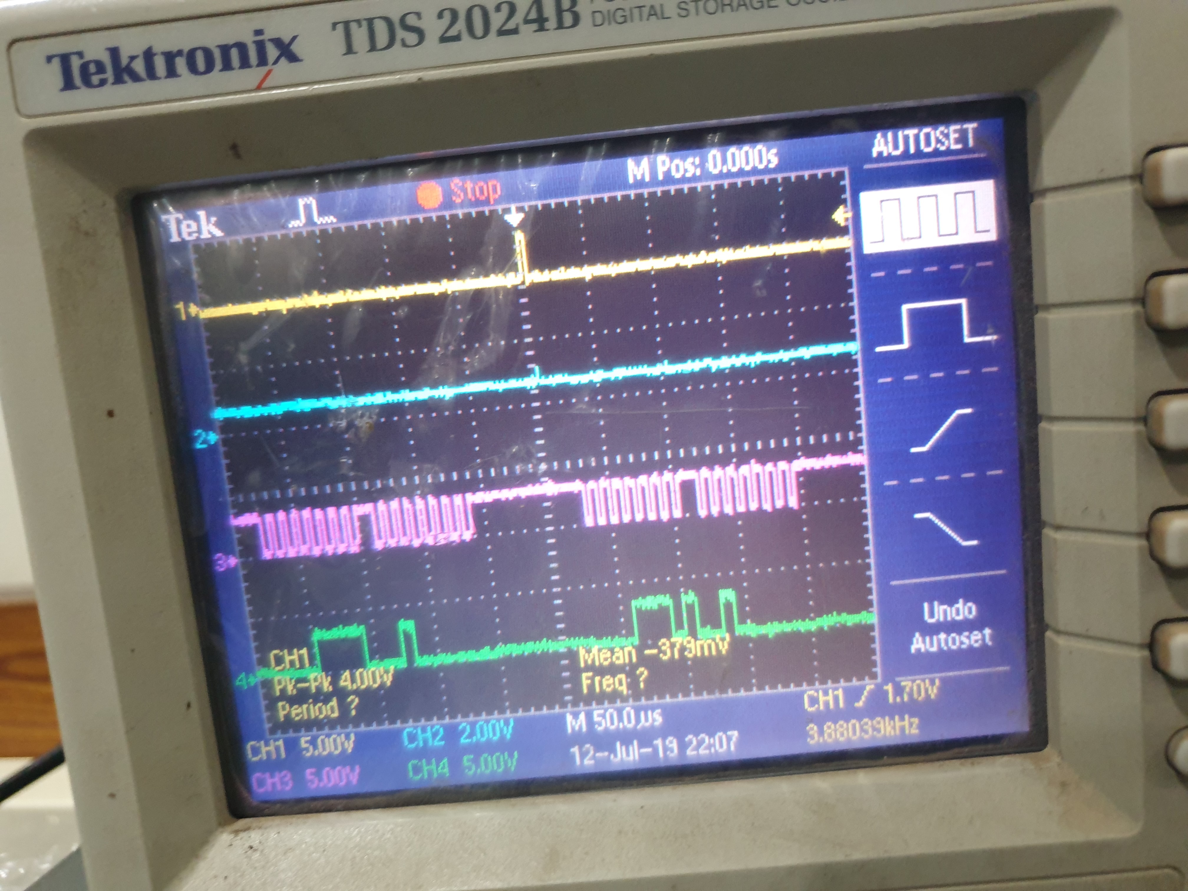
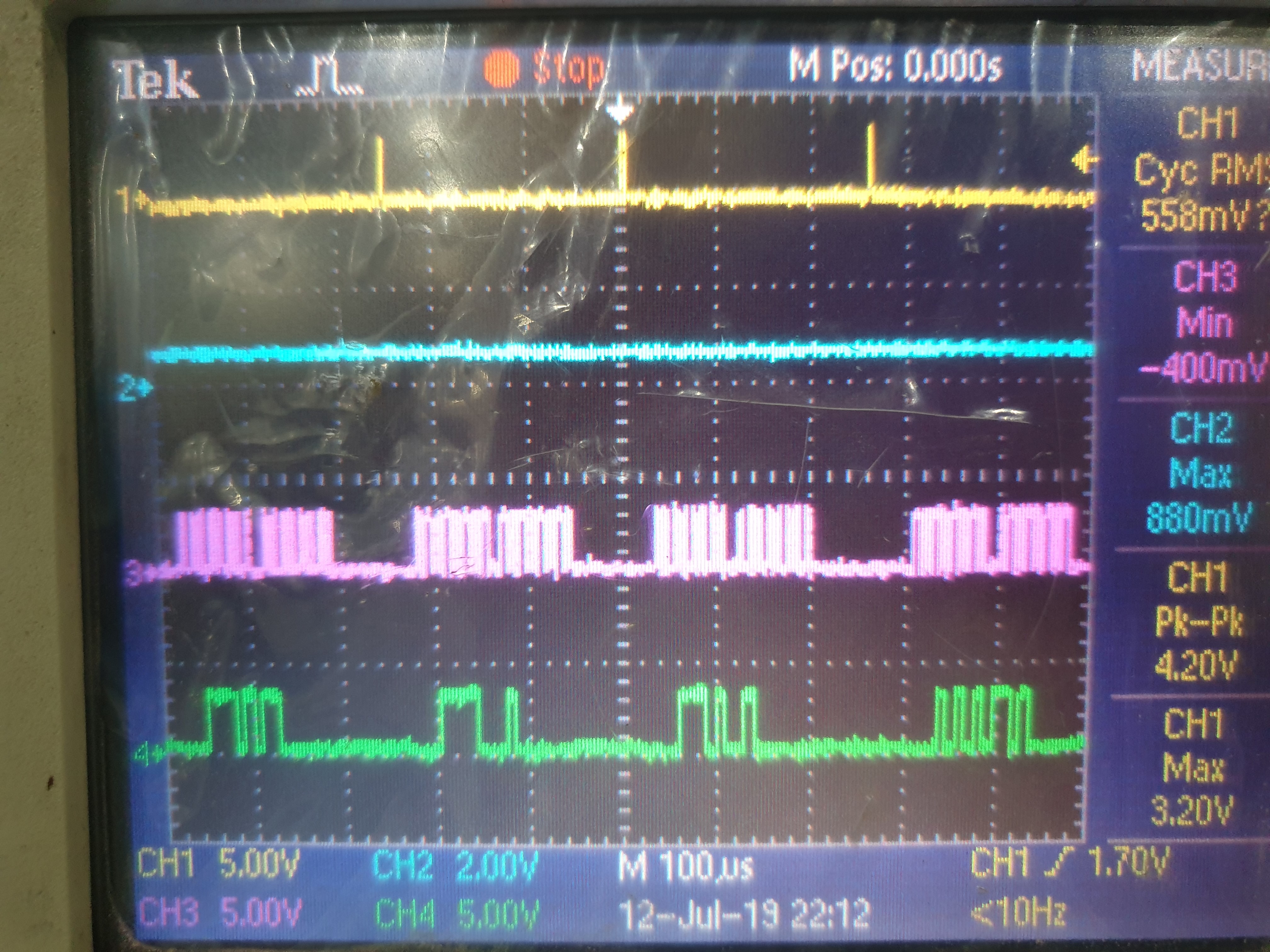
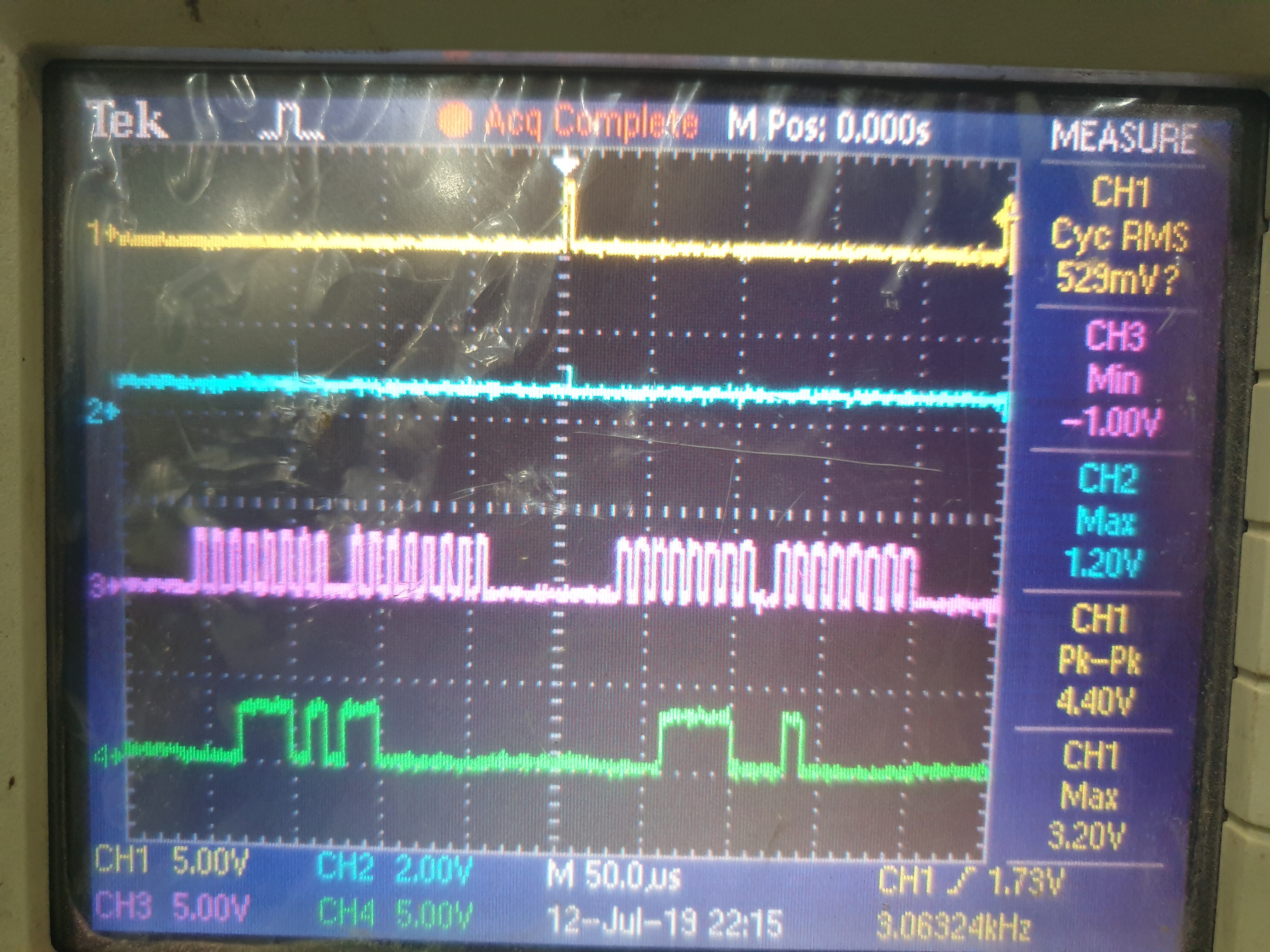
Oscilloscope capture - (CH1 - MOSI - Yellow) (CH2 - MISO - BLUE) (CH3- SCK - PINK) (CH4 - CS# - GREEN)

IMAGE1 - shows only one frame

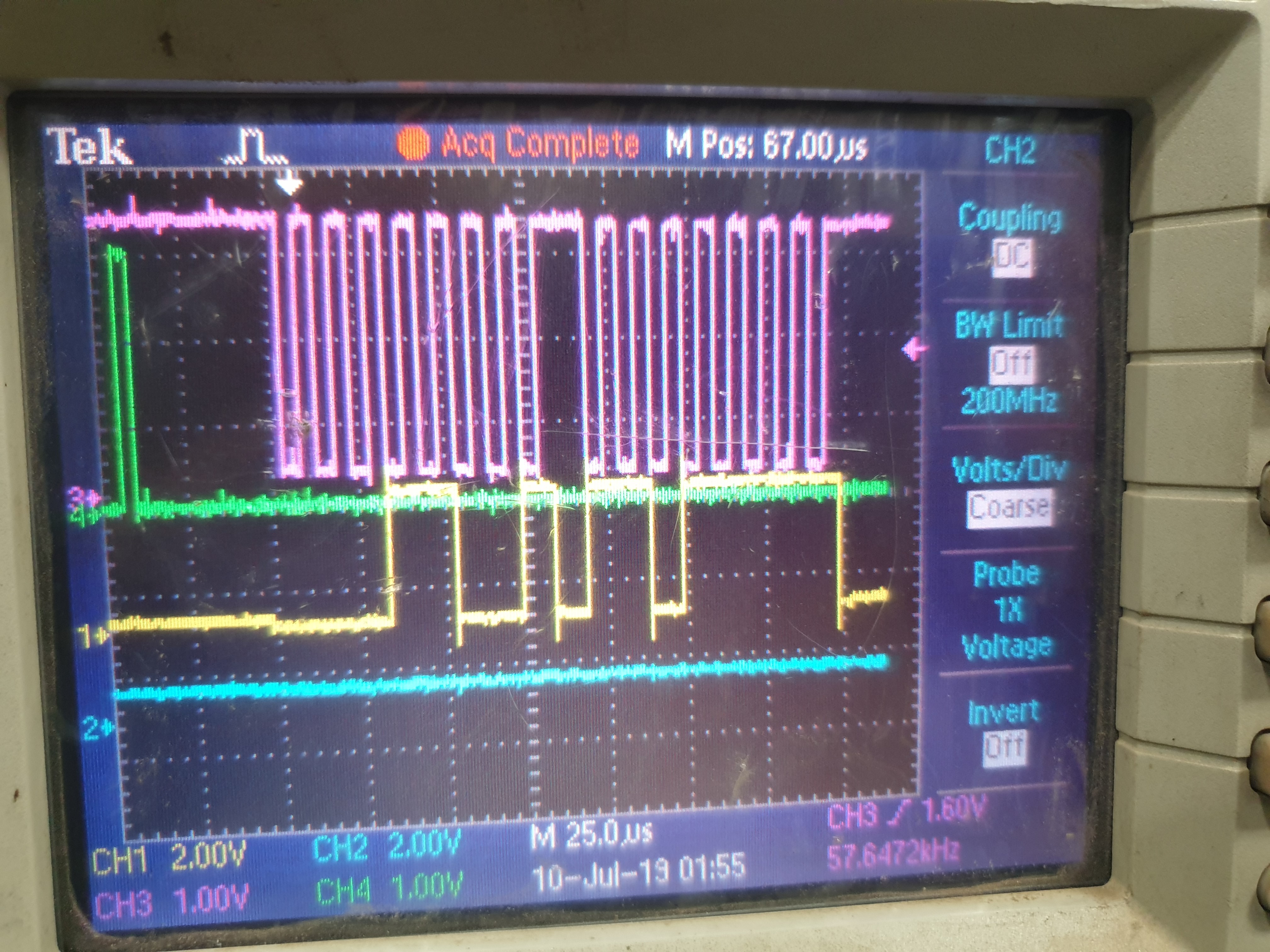
IMAGE2 - Shows 3 frames

IMAGE3 - Shows two frames in detail.

Program ADC program - 

def build_adc_command(mode, en_prog, next_channel, vref_change, operation, channel_gpio, gpio_dat):
    command = ((mode & 0x0F) << 12) | ((en_prog & 0x01) << 11) | ((next_channel & 0x0F) << 7) |\
              ((vref_change & 0x01) << 6) | ((operation & 0x01) << 5) | ((channel_gpio & 0x01) << 4) |\
              (gpio_dat & 0x0F)
    # print(command)
    return [((command >> 8) & 0xFF), (command & 0xFF)]

NUM_CH = 16

if __name__ == '__main__':
    adcValues = [0 for i in range(NUM_CH)]
    spi = spidev.SpiDev()
    spi.open(0, 1)
    spi.max_speed_hz = 1000000
    spi.mode = 0b11
    spi.cshigh = False
    spi.lsbfirst = False
    spi.bits_per_word = 8
    spi.no_cs = True
    GPIO.setmode(GPIO.BOARD)
    GPIO.cleanup()
    # setmode to input
    # setmode to output
    GPIOsetup(26, GPIO.OUT)
    reset = False

    while 1:
        try:
            time.sleep(0.25)  # 10 hz output
            # 0b00011101
            # 0b10000000
            # for ch in range(0, 7):
            # spi.xfer([0b00011101, 0b10000000])
            if reset is False:
                GPIO.output(26, GPIO.LOW)
                time.sleep(0.01)
                adcValues = spi.xfer2([0x42, 0x0f])
                time.sleep(0.001)
                GPIO.output(26, GPIO.HIGH)
                reset = True
            time.sleep(0.001)
            GPIO.output(26, GPIO.LOW)
            adcValues = spi.xfer2(build_adc_command(0b0001, 0b1, 0b1011, 0b1, 0b0, 0b1, 0b0000))
            print("xfer return Values 1 = ", adcValues)
            time.sleep(0.001)
            GPIO.output(26, GPIO.HIGH)
            time.sleep(0.001)
            GPIO.output(26, GPIO.LOW)
            adcValues = spi.xfer2(build_adc_command(0b0001, 0b1, 0b0001, 0b1, 0b0, 0b1, 0b1111))
            print("xfer return Values 2 = ", adcValues)
            time.sleep(0.001)
            GPIO.output(26, GPIO.HIGH)
            time.sleep(0.001)
            GPIO.output(26, GPIO.LOW)
            adcValues = spi.xfer2(build_adc_command(0b0001, 0b1, 0b0010, 0b1, 0b0, 0b1, 0b0000))
            print("xfer return Values 3 = ", adcValues)
            time.sleep(0.001)
            GPIO.output(26, GPIO.HIGH)
            time.sleep(0.001)
            GPIO.output(26, GPIO.LOW)
            adcValues = spi.xfer2(build_adc_command(0b0001, 0b1, 0b0011, 0b1, 0b0, 0b1, 0b1111))
            print("xfer return Values 4 = ", adcValues)
            time.sleep(0.001)
            GPIO.output(26, GPIO.HIGH)
        except KeyboardInterrupt:
            break


After going through above information, my problems are

1. ADC MISO pin always in tri-state even giving pull up.

2. Is the command sent are correct?

3. Not even junk data coming from MISO pin.

Kindly provide a solution at the earliest. 

  • hello,
    Does this only happen when sampling channel 11? do the other channels function correctly? Also, can you make sure there is nothing else on this line that could be driving it low by mistake, a possible short.

    Can you try providing the following commands, and take a scope shot the of the three frames
    Be sure that the input of channel 10, 11, 12 are known DC values

    0001 1 1010 100 0000  = 1D40xh

    0001 1 1011 100 0000  = 1DC0xh
     
    0001 1 1100 100 0000  = 1E40xh

    Regards

    Cynthia

  • Hi Cynthia,

    Thank you for your reply. As per your reply,

    1. Other channel also returns the same data i.e no activity on SDO pin of ADC it is in tri-state.

    2. The SDO line was connected to tri-state buffer (p/n-SN74LVC244APWR) thorough 22E series resistor. But when we found this problem, I removed the series resistor. So now the SDO line is directly connected to the host.

    As per your request I have sent the following command as per your suggesting. 

    CH10 and CH12 are 3.3V and CH11 = 4.098V.

    No activity on SDO line. Find the attached image file. I have tested both SPI mode 0 and mode 3.

    (CH1/Yellow/Chip select)

    CH2/Blue/SDO/MISO

    CH3/pink/SCLK

    CH4/Green/SDI/MOSI

  • Dear All,

    It has been more than 2 days after posting the asked results, still no reply. Is there a solution to this problem ??

    Kindly let me know ASAP.

  • Hello,

    This looks like it is external to the device. The SDO line is being held at a steady voltage above ground.

    Would it be possible to have the SDO pin of the device floating, not connected to anything, including the host? and only monitor it with the oscilloscope, and run the same commands?

    I believe there is something on the board that is holding the SDO line, or perhaps the host itself is causing this.

    Regards

    Cynthia

  • Dear Cynthia,

    The problem is finally resolved. Sorry the for the late info.

    1. After your input on connecting known voltage to CH10, 11 and 12. I tried to read the ADC, no change on the SDO line of ADC.

    2. We changed the host setup instead of RPI 3b+ board, we connected a SPI port of NXP based development board. The ADC showed the same response.

    3. Finally we changed the ADC (replaced it with new one). Then it worked, no change in circuit.

    For now the issue is resolved. How ever on complete integration of the system I can check all other channel and confirm.

    Kindly close the issue. For future assistance I might reopen this thread. 

    Thank you for your support.

    Cheers,

    Eashwar