This thread has been locked.

If you have a related question, please click the "Ask a related question" button in the top right corner. The newly created question will be automatically linked to this question.

AMC1304M25: AMC1304M25 which max current can we measure

Part Number: AMC1304M25
Other Parts Discussed in Thread: AMC1304M05

Hello

We use the AMC1304 to measure current in Brusless motor phase. (Like preconised into IDDK)

We used it with success up to 25A with a Shunt resistor of 0.01Ohm.

Now we want increase our calibre and then increase the measurable current.

Is acceptable to use a shunt resistor of 0.002Ohm then measure up to 125A?

What is your opinion?

Regards

  • Hi,

    Shunt selection at currents this high can be challenging due to the tradeoff of V=IR for input voltage and P=I^2R, power dissipated in the shunt resistor. 

    To measure up to 125A (Assuming this is maximum current), I would suggest the 50mV input version of the device, AMC1304M05 and a shunt resistance of 400uohm.  

    Just to confirm a few things so I can offer additional guidance:

    What is the nominal (steady-sate) current to be measured?

    What is the maximum current to be measured?

    What is the expected transient/safety limiting current?  

    What is your accuracy requirement for the nominal measurement and is it relaxed at higher currents? 

    Will your employ a heat sink or fan to help reduce the self-heating affects of the shunt resistor? 

    Do you plan on performing any calibration? 

  • Hello

    Thank for your back.

    1) I don't understand what you advise the 50mV version instead of 250mV version. This will lead to a smaller shunt value, then we will lost into accuracy (Due to contact resistor) and maybe have more noise?

    2) What is the nominal (steady-sate) current to be measured?

    It is for a brushless drive up to 40A nominal into the motor. So we estimate a current into the motor which vary between -40A and +40A RMS, then up to 56.56A instantaneous.

    What is the maximum current to be measured?

    Our drive assume a temporary current (max 2s) up to twice the nominal current. Then our drive will be a 40A RMS nominal / 80A RMS max 2s. => 80x1.41 = 113. We take a margin of 10 to 20% (due to motor pic, noise into cable etc..) Then we want assume to measure up to 125A instantaneous.

    3) What is the expected transient/safety limiting current?  If we reach 125A, we trig an over current error.

    4) What is your accuracy requirement for the nominal measurement and is it relaxed at higher currents?

    I never take care to this question. We evaluate AMC1304 on the IDDK demo board for a 5A motor. The result was ok for use up to 30meter cable length. More we will have accuraccy, better the control motor will be.

    5) Will your employ a heat sink or fan to help reduce the self-heating affects of the shunt resistor? 

    I'm not Wooried for the dissipation into the resistor. We will adjust the shunt dissipation/Power according our need. We also can place many resistor Serial/parrallal..

    6) Do you plan on performing any calibration? 

    Like the Iddk done, we sample the current on the start to set a zero offset.

    Until today, on our drive version 4A, 5A, 8A we never need to calibrate. We plan to do the 16A version and then the 40A. If you think we need to make a calibration, we could make it at the end of our manufature. But I in this case, we could evaluate some other solution which will not require calibration.

  • Thank you for the additional details. 

    I would expect the noise in the system to be the same, so you are correct that with a smaller input range the SNR will decrease. The reason I recommend this is due to the tradeoff between V=IR and P=I^2R in the shunt resistor. The power dissipation creates a tradeoff between maximizing full-scale input range, accuracy and heat dissipation. If you have adequate means to dissipate the heat and accuracy is the utmost concern then the 250mV version will be best for you. 

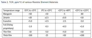
    Depending on the material used for your shunt resistor, you may start to see large drift once the temperature difference between the hot spot of the sensing element and the terminal goes beyond 60C. As you said, you can increase the wattage of the shunt resistor or upgrade the gauge of your cables as needed. 

    Calculating for resistance with a maximum current of 125A: 

    V = 250mV; R = 2mohm ; V = 50mV; R = 400uohm

    IEEE standards specify that the shunt resistor should not run more than 2/3 of rated current for continuous operation. Calculating recommended rated resistor wattage and short term overload wattage follow as below:

    Nominal = 40A; * 3/2 = 60A and calculating resistor wattage:

    V = 250mV; W = 60^2*2mohm = 7.2W ; V = 50mV; W = 60^2*400uohm = 1.5W

    Maximum = 125A and calculating resistor wattage for short term overload:

    V = 250mV; W = 125^2*2mohm = 31.3W ; V = 50mV; W = 120^2*400uohm = 6.3W 

  • Hello,

    Ok, then for you, the main point to take care is the heating of the resistor due to the resistor heating, I'm right?

    On the start, my concern was on the very low value of resistance vs solder contact, Pad .. resistor value.

    Then 400µohm seems to me very low but had the advantage to reduce the power.

  • Hi,

    For highest accuracy measurements without drift and loss of accuracy due to self-heating effects, yes. 

    As the wattage of the resistor increases, the price increases as well which is another concern. Similarly for the additional heat mitigation techniques such as increasing the size of the conductor or increasing the weight of the PCB copper. These solutions increase the cost of each unit produced. 

    Very low resistance vs solder pad contact is a challenge too, however it is something that can be handled up front during development and the solution will not increase the cost of each unit. I recommend making a "Coupon card" shunt test PCB with multiple (4, 8, or 16) of the shunt resistor's recommended layouts and a few test points for each. Two test points for primary current through each shunt and two test points for sensing. Then work with your manufacturing team and ask to try a few different solder profiles on these cards, a different solder profile for each card. Test and compare performance of the different solder profiles to identify which profile produces the highest accuracy measurement. Once the best solder profile is identified the performance will be very consistent and the only remaining variable will be shunt tolerance. 

  • Hi,

    Thank for your advice.

    I think I will try to use only one resistor, because parrallale resistor has a risk of bad measure du to PCB strip line between each resistor (this will add no controlled resistor value).

  • Hi,

    My pleasure I hope it was beneficial for you. Please don't hesitate to reach out if you have further questions and I would be interested to hear how it goes for you. 

    Yes putting resistors in parallel has the advantage of each resistor can have a lower rated wattage, but ultimately the same amount of heat is dissipated to the PCB. Theoretically, it could have the advantage of reducing error due to shunt resistor tolerance. i.e. if you have two resistors in parallel, one with a +1% tolerance and one with a -1% tolerance, they cancel out. Your margin for maximum error does increase though as you could have two resistors with +1% tolerance. Additionally, the layout will be more complicated and take up more area. 

    Clarifying the coupon card with multiple resistors, I did not mean putting them in parallel. I meant having multiple resistors on the coupon card and testing the performance of each resistor to guarantee high performance measurements over resistor tolerance variation. If you test only one shunt resistor per solder profile, your results may not be as consistent!